U RX-V530/RX-V430 AV Receiver OWNER’S MANUAL 0100V530(U)-cv1 1 12/27/01, 10:30 PM
SAFETY INSTRUCTIONS 10 CAUTION RISK OF ELECTRIC SHOCK DO NOT OPEN CAUTION: TO REDUCE THE RISK OF ELECTRIC SHOCK, DO NOT REMOVE COVER (OR BACK). NO USER-SERVICEABLE PARTS INSIDE. REFER SERVICING TO QUALIFIED SERVICE PERSONNEL.
SAFETY SAFETY INSTRUCTIONS INSTRUCTIONS d) 20 21 22 23 If the product does not operate normally by following the operating instructions.
CAUTION: READ THIS BEFORE OPERATING YOUR UNIT. 1 To assure the finest performance, please read this manual carefully. Keep it in a safe place for future reference. 13 To prevent damage by lightning, disconnect the power cord from the wall outlet during an electrical storm.
INTRODUCTION CONTENTS INTRODUCTION CONTENTS ............................................................ 1 FEATURES ............................................................. 2 GETTING STARTED ............................................ 3 Checking the package contents ................................. 3 Installing batteries in the remote control ................... 3 CONTROLS AND FUNCTIONS ......................... 4 PREPARATION SPEAKER SETUP .................................................
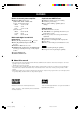
FEATURES Built-in 5-channel power amplifier Sophisticated AM/FM Tuner ◆ Minimum RMS output power (0.06% THD, 20 Hz – 20 kHz, 8Ω) [U.S.A.
GETTING STARTED INTRODUCTION Checking the package contents Check your package to make sure it contains the following items.
CONTROLS AND FUNCTIONS Front panel 1 2 3 4 5 6 7 VOLUME INPUT INPUT M0DE 6CH INPUT NATURAL SOUND AV RECEIVER STANDBY /ON BASS TREBLE SILENT STEREO PROGRAM EFFECT MEMORY TUNING MODE MAN'L/AUTO FM AUTO/MAN'L MONO FM/AM PRESET/TUNING PRESET/TUNING A/B/C/D/E EDIT – PHONES 9 8 0 q w e r t y + u – + i 1 STANDBY/ON 4 INPUT MODE Turns this unit on, or set it to the standby mode.
CONTROLS AND FUNCTIONS 8 9 STEREO/EFFECT Switches between normal stereo and DSP effect reproduction. When STEREO is selected, 2-channel signals are directed to the main left and right speakers without effect sounds and all Dolby Digital and DTS signals (except the LFE channel) are mixed down to the main left and right speakers. u BASS Adjusts the low-frequency response for the main left and right channels. Turn right to increase or turn left to decrease the lowfrequency response.
CONTROLS AND FUNCTIONS Remote control This section describes the remote control controls and their functions. Make sure that the AMP mode is selected before starting operation. See “REMOTE CONTROL FEATURES” on pages 46 to 48. 1 2 TRANSMIT CODE SET SYSTEM STANDBY POWER POWER TV AV CD MD/CD-R TUNER SLEEP DVD D-TV/CBL V-AUX 6CH INPUT 9 3 Input selector buttons 0 Select the input source and set the remote control to operate the selected source component.
CONTROLS AND FUNCTIONS y MUTE Mutes the sound. Press again to restore the audio output to the previous volume level. Using the remote control Switches between normal stereo and DSP effect reproduction. When STEREO is selected, 2-channel signals are directed to the main left and right speakers without effect sounds and all Dolby Digital and DTS signals (except the LFE channel) are mixed down to the main left and right speakers.
CONTROLS AND FUNCTIONS Front panel display 1 2 MATRIX VCR DIGITAL VIRTUAL SILENT PRO LOGIC / V-AUX D-TV/CBL 3 DVD DTS DOLBY DIGITAL PRO LOGIC MOVIE THTR 12 ENTERTAINMENT MD/CD-R TUNER CD STEREO AUTO MUTE VOLUME TUNED MEMORY SLEEP L DSP dB mS PCM 5 4 6 7 8 9 C R LFE RL RC RR 0 q w e r t 1 Processor indicators 9 Multi-information display Lights up when the t, g, VIRTUAL, PRO LOGIC / , DSP or MATRIX are activated.
PREPARATION SPEAKER SETUP Speaker placement The main speakers are used for the main source sound plus effect sounds. They will probably be the speakers from your present stereo system. The rear speakers are used for effect and surround sounds. The center speaker is for the center sounds (dialog, vocals, etc.). Rear speaker (R) Subwoofer Main speaker (L) 1.8 m (6 feet) Rear speaker (L) ■ Main speakers Place the main left and right speakers an equal distance from the ideal listening position.
SPEAKER SETUP Connecting the speakers Be sure to connect the left channel (L), right channel (R), “+” (red) and “–” (black) properly. If the connections are faulty, no sound will be heard from the speakers, and if the polarity of the speaker connections is incorrect, the sound will be unnatural and lack bass. CAUTION • Use speakers with the specified impedance shown on the rear panel of this unit. • Do not let the bare speaker wires touch each other or any metal part of this unit.
SPEAKER SETUP Main speaker Right Left 2 INTRODUCTION 1 Center speaker 3 (RX-V530) CENTER DIGITAL INPUT 6CH INPUT VIDEO AUDIO MAIN + L R S VIDEO VIDEO CD V-AUX SURROUND TUNER – AM ANT CENTER IN PR/CR VCR PB/CB Y DVD 75Ω UNBAL.
SPEAKER SETUP ■ IMPEDANCE SELECTOR switch WARNING Do not change setting of the IMPEDANCE SELECTOR switch when the power of this unit is on, this may damage the unit. If this unit fails to turn on when STANDBY/ON (or SYSTEM POWER) is pressed, the IMPEDANCE SELECTOR switch may not be fully slid to either position. If so, slide the switch all the way to either position when this unit is in the standby mode. Select the switch position (left or right) according to the impedance of the speakers in your system.
CONNECTIONS This unit has digital jacks for direct transmission of digital signals through either coaxial or fiber optic cables. You can use the digital jacks to input PCM, Dolby Digital and DTS bitstreams. To enjoy multi-channel sound track of DVD software, etc. with DSP effect, you need to make digital connection. All digital input jacks are acceptable for 96-kHz sampling digital signals.
CONNECTIONS Connecting video components Refer to the connection examples on the next page. ■ Types of video jacks RX-V530 There are three types of video jacks as follows: COMPONENT VIDEO S VIDEO VIDEO PR/CR PB/CB Y ■ Connecting a digital TV/cable TV Connect the video signal output jack on the component to the VIDEO jack on this unit. RX-V530 Connect the optical digital audio signal output jack on your component to the DIGITAL INPUT jack on this unit.
CONNECTIONS O OPTICAL OUTPUT RX-V530 Another video component VCR AUDIO INPUT AUDIO OUTPUT R L L 6CH INPUT V R AUDIO VIDEO OUTPUT L V TV/digital TV/ cable TV R V VIDEO OUTPUT V PREPARATION DIGITAL INPUT AUDIO OUTPUT VIDEO VIDEO OUTPUT INPUT AUDIO OUTPUT VIDEO MAIN L R S VIDEO VIDEO CD V-AUX SURROUND COAXIAL TUNER AM ANT CENTER SUB WOOFER OPTICAL D-TV/CBL IN COMPONENT VIDEO PR/CR PB/CB BASIC OPERATION GND VCR Y DVD DVD OUT CD 75Ω UNBAL.
CONNECTIONS Connecting audio components ■ Connecting a CD player Connect the coaxial digital output jack on your CD player to the DIGITAL INPUT CD jack. y • The AUDIO jacks are available for a CD player which does not have coaxial digital output jack. ■ Connecting a CD recorder or MD recorder y RX-V530 • The AUDIO jacks are available for an CD recorder or MD recorder which does not have optical digital input or output jack.
CONNECTIONS Connecting the antennas ■ Connecting the AM loop antenna Set up the AM loop antenna, then connect it. 2 Press and hold the tab to insert the AM loop antenna lead wires into the AM ANT and GND terminals. 3 Orient the AM loop antenna for the best reception. Connect each antenna correctly to the designated terminals.
CONNECTIONS Connecting an external decoder This unit is equipped with 6 additional input jacks (MAIN left and right, CENTER, SURROUND left and right and SUBWOOFER) for discrete multi-channel input from an external decoder, sound processor, or pre-amplifier. Connect the output jacks on your external decoder to the 6CH INPUT jacks. Be sure to match the left and right outputs to the left and right input jacks for the main and surround channels.
CONNECTIONS Turning on the power INTRODUCTION When all connections are complete, turn on the power of this unit.
SPEAKER MODE SETTINGS This unit has 5 SPEAKER SET items on the SET MENU that you must set according to the number of speakers in your configuration and their size. The following table summarizes these SPEAKER SET items, and shows the initial settings as well as other possible settings. If the initial settings shown in the following table are not appropriate for your speaker configuration, see “1 SPEAKER SET” on pages 41-42 to change the settings.
ADJUSTING SPEAKER OUTPUT LEVELS Note 3 Set the BASS and TREBLE controls on the front panel to the center position and adjust the volume of this unit so you can hear the test tone. The test tone is heard (in order) from the main left speaker, center speaker, main right speaker, rear right speaker, rear left speaker, and the subwoofer. The tone is produced for 2.5 seconds from each speaker.
ADJUSTING SPEAKER OUTPUT LEVELS 4 Adjust the level of the effect speakers using j / i so that it matches the level of the main speakers. While adjusting, the test tone is heard from the selected speaker. PRESET/CH – SELECT + Note • To adjust the level of the main speakers, use VOLUME knob (or VOLUME +/– on the remote control). 5 When adjustment is complete, press TEST to stop the test tone.
BASIC PLAYBACK 3 5 3 VOLUME INPUT INPUT M0DE 6CH INPUT NATURAL SOUND AV RECEIVER STANDBY /ON BASS 3 Press INPUT l / h repeatedly (one of the input selector buttons on the remote control) to select the input source. The selected input source name and input mode appear on the front panel display for a few seconds.
BASIC PLAYBACK 4 5 Start playback or select a broadcast station on the source component. Refer to the operation instructions for the component. Adjust the volume to the desired level. The volume level is displayed digitally. Example: –70 dB Control range: VOLUME MUTE (minimum) to 0 dB (maximum) The volume level indicator also shows the current volume level as a bar graph. If desired, use BASS and TREBLE. These controls only effect the sound from the main speakers.
BASIC PLAYBACK ■ Notes on 96-kHz sampling digital signals Input modes and indications Each time you turn on the power of this unit, the input mode is set according to “8 INPUT MODE” setting on the SET MENU (see page 45 for details).
BASIC PLAYBACK 3 Selecting a sound field program You can enhance your listening experience by selecting a DSP program. For details about each program, see pages 29 to 33. After selecting the desired program, press the same button repeatedly to select the desired sub-program if available. Example: Pressing MOVIE THEATER 1 repeatedly switches the sub-program between “Sci-Fi” and “Spectacle”.
BASIC PLAYBACK ■ Selecting PRO LOGIC 4 HALL JAZZ CLUB ROCK CONCERT 1 2 3 4 TV SPORTS MONO MOVIE MOVIE THEATER 1 MOVIE THEATER 2 5 VOLUME INPUT Press SELECT repeatedly to select the decoder; PRO LOGIC or PRO LOGIC . INPUT M0DE ENTERTAINMENT 6 7 8 SELECT MATRIX 6.1 STEREO 0 +10 6CH INPUT /DTS SUR.
BASIC PLAYBACK ■ Playing Dolby Digital Surround EX or DTS ES software ■ SILENT CINEMA DSP Press MATRIX 6.1 to turn on the Dolby Digital + Matrix 6.1 or DTS + Matrix 6.1 decoder. MATRIX MATRIX 6.1 VCR V-AUX D-TV/CBL DVD MD/CD-R TUNER DIGITAL MOVIE THTR 1 +10 Spectacle 6.1 DSP The MATRIX indicator lights up. The display changes AUTO → Matrix6.1 → OFF each time the MATRIX 6.1 button is pressed. AUTO: Matrix6.1: OFF: This mode automatically switches Dolby Digital + Matrix 6.
DIGITAL SOUND FIELD PROCESSING (DSP) PREPARATION A sound field is defined as the “characteristic sound reflections of a particular space.” In concert halls and other music venues, we hear early reflections and reverberations as well as the direct sound produced by the artist(s). The variations in the early reflections and other reverberations among the different music venues is what gives each venue its special and recognizable sound quality.
CINEMA-DSP Sound design of CINEMA-DSP Filmmakers intend for the dialog to be located right on the screen, the effect sound a little farther back, the music spread even farther back, and the surround sound around the listener. Of course, all of these sounds must be synchronized with the images on the screen. CINEMA-DSP is an upgraded version of YAMAHA DSP specially designed for movie soundtracks.
CINEMA-DSP ■ Dolby Digital/DTS + DSP sound field effect Left surround DSP sound field Right surround DSP sound field ■ Dolby Digital/DTS + Matrix 6.1 + DSP sound field effect ■ Dolby Pro Logic + DSP sound field effect Surround DSP sound field ADDITIONAL INFORMATION ■ Dolby Pro Logic ADVANCED OPERATION Most movie software has 4-channel (left, center, right, and surround) sound information encoded by Dolby Surround matrix processing and stored on the left and right tracks.
CINEMA-DSP CINEMA-DSP programs ■ For movie programs: No. 7 to 9 This unit automatically chooses the appropriate decoder and DSP sound field pattern according to the input signal format. Table of Program Names for Each Input Format Input No. 2 channel 5.1 channel 6.1 channel * Stereo DOLBY DIGITAL DTS DOLBY DIGITAL Matrix 6.1 DTS Matrix 6.1 70 mm Spectacle DGTL Spectacle DTS Spectacle Spectacle 6.1 Spectacle 6.1 70 mm Sci-Fi DGTL Sci-Fi DTS Sci-Fi Sci-Fi 6.1 Sci-Fi 6.
CINEMA-DSP The following list gives you a brief description of the sound fields produced by each of the DSP programs. Keep in mind that most of these are precise digital recreations of actual acoustic environments. Select the DSP program that you feel sounds best regardless of the name and description given for it below. 7 MOVIE THEATER 2 This program creates the extremely wide sound field of a 70-mm movie theater.
TUNING 4 Automatic and manual tuning There are 2 ways to tune; automatic and manual. Automatic tuning is effective when station signals are strong and there is no interference. Press PRESET/TUNING l / h once to begin automatic tuning. Press h to tune in to a higher frequency, or press l to tune in to a lower frequency.
TUNING Notes Presetting stations VOLUME INPUT INPUT M0DE 6CH INPUT NATURAL SOUND AV RECEIVER STANDBY /ON BASS TREBLE SILENT STEREO PROGRAM EFFECT MEMORY TUNING MODE MAN'L/AUTO FM AUTO/MAN'L MONO FM/AM PRESET/TUNING PRESET/TUNING A/B/C/D/E EDIT – PHONES + – + 1 Press FM/AM to select the FM band. FM/AM 2 TUNING MODE AUTO AUTO/MAN'L MONO 3 Lights up ADDITIONAL INFORMATION Press and hold MEMORY (MAN’L/AUTO FM) for more than 3 seconds.
TUNING ■ Manually presetting stations 4 You can also store up to 40 stations (8 stations x 5 groups) manually. VOLUME INPUT INPUT M0DE 6CH INPUT NATURAL SOUND AV RECEIVER Press PRESET/TUNING l / h to select a preset station number (1 to 8) while the “MEMORY” indicator is flashing. Press h to select a higher preset station number. Press l to select a lower preset station number.
TUNING Tuning in to a preset station Exchanging preset stations You can exchange the assignment of two preset stations. The example below describes the procedure for exchanging preset station “E1” with “A5”. INTRODUCTION You can tune any desired station simply by selecting the preset station number under which it was stored.
SLEEP TIMER Use this feature to automatically set this unit in the standby mode after the amount of time you have set. The sleep timer is useful when you are going to sleep while this unit is playing or recording a source. The sleep timer also automatically turns off the external component(s) connected to AC OUTLET(S). Canceling the sleep timer 1 The sleep timer can only be set with the remote control. y Press SLEEP repeatedly until “SLEEP OFF” appears on the front panel display.
RECORDING 1 2 VOLUME INPUT INPUT M0DE 6CH INPUT NATURAL SOUND AV RECEIVER STANDBY /ON STEREO PROGRAM EFFECT FM/AM MEMORY TUNING MODE MAN'L/AUTO FM AUTO/MAN'L MONO PRESET/TUNING PRESET/TUNING TREBLE A/B/C/D/E EDIT – + – + TRANSMIT CODE SET SYSTEM 2 STANDBY POWER POWER TV AV CD MD/CD-R TUNER SLEEP DVD D-TV/CBL V-AUX 6CH INPUT VCR A B AMP POWER + + TV CH VOLUME – – TV MUTE TV INPUT ■ Special considerations when recording DTS software – MUTE HALL JAZZ CL
ADVANCED OPERATION SET MENU The SET MENU consists of 10 items including the speaker mode setting. Choose the appropriate item and adjust or select the values as necessary. Adjusting the items on the SET MENU y • You can adjust the items on the SET MENU while playing a source. Items 1 Adjustment should be made with the remote control.
SET MENU 5 Press j / i repeatedly to change the setting of the item. PRESET/CH – + SELECT 1 SPEAKER SET (speaker mode settings) 6 Press u/d repeatedly until the menu disappears or simply press one of the DSP program group buttons to exit SET MENU. PRESET/CH – SELECT + or HALL JAZZ CLUB ROCK CONCERT 1 2 3 4 TV SPORTS MONO MOVIE MOVIE THEATER 1 MOVIE THEATER 2 5 9 6 7 8 SELECT MATRIX 6.
SET MENU ■ 1B MAIN (main speaker mode) ■ 1D BASS (LFE/bass out mode) Choices: LARGE, SMALL LFE signals carry low-frequency effects when this unit decodes a Dolby Digital or DTS signal. Low-frequency signals are defined as 90 Hz and below. The Lowfrequency signals can be directed to both main left and right speakers, and the subwoofer (subwoofer can be used for both stereo reproduction and the DSP program). LARGE Select this if you have large main speakers.
SET MENU 2 LFE LEVEL Control range: SPEAKER ............ –20 to 0 dB HEADPHONE ..... –20 to 0 dB Initial setting: 0 dB Press d/u to select the item to be adjusted. 2 Press j to adjust the LFE level. Note • Adjust the LFE level according to the capacity of your subwoofer or headphones. 1 Press j / i to increase or decrease the delay of the center channel sounds.
SET MENU 4 D. RANGE (dynamic range) Use this feature to adjust the dynamic range. This setting is effective only when this unit is decoding Dolby Digital signals. Choices: MAX, STD (standard), MIN (minimum) MAX Select the “MAX” for feature films. STD Select the “STD” for general use. MIN Select the “MIN” for listening to sources at low volume levels.
SET MENU 8 INPUT MODE (initial input mode) INTRODUCTION Use this feature to designate the input mode for sources connected to the DIGITAL INPUT jacks when you turn on this unit (see page 25 for details about the input mode). Choices: AUTO, LAST PREPARATION AUTO Select this to allow this unit to automatically detect the type of input signal and select the appropriate input mode. LAST Select this to set this unit to automatically select the last input mode used for the respective source.
REMOTE CONTROL FEATURES In addition to controlling this unit, the remote control can operate other A/V components made by YAMAHA and other manufacturers. To control other components, you must set up the remote control with the manufacturer codes. Control area ■ Controlling this unit ■ Controlling other component The shaded areas below can be used to control this unit when the AMP mode is selected. Press AMP to select the AMP mode. The shaded areas below can be used to control other components.
REMOTE CONTROL FEATURES Setting the manufacturer code The following table shows factory-set component (Library: component category) and the manufacturer code for each component control. Component category (Library) Manufacturer CD CD YAMAHA 0005 MD/CD-R MD YAMAHA 0024 TUNER TUNER YAMAHA 0003 1 Press an input selector button or Å/ı to select the component control for which you want to clear the manufacturer code.
REMOTE CONTROL FEATURES Controlling other components You can operate other components when you have set the manufacturer code for your component. Note, however, that some buttons may not operate your component. Once you select an input source, the remote control switches to the mode for operating the component.
ADJUSTING THE LEVEL OF THE EFFECT SPEAKERS 3 Adjustment should be made with the remote control. Press j / i to adjust the speaker output level. • The control range for the center or rear left and right speakers is from +10 dB to –10 dB. • The control range for the subwoofer is from 0 dB to –20 dB.
ADJUSTING THE DELAY TIME You can adjust the time difference between the beginning of the sound from the main speakers and the beginning of the sound effect from the rear speakers. The larger the value, the later the sound effect is generated. The delay time can be individually adjusted to all DSP programs. Adjustment should be made with the remote control. TRANSMIT CODE SET SYSTEM POWER POWER TV AV CD MD/CD-R DVD D-TV/CBL VCR 1 The following table shows factory-set delay time. 1. 2. 3. 4. 5.
ADJUSTING THE PARAMETER SETTINGS FOR PRO LOGIC You can adjust the values of PRO LOGIC Music parameters so the sound fields are recreated accurately in your listening room. Adjustments should be made with the remote control. TRANSMIT CODE SET SYSTEM AV CD MD/CD-R DVD VCR 1 D-TV/CBL A STANDBY POWER TUNER SLEEP MUTE V-AUX 6CH INPUT JAZZ CLUB ROCK CONCERT 1 2 3 4 TV SPORTS MONO MOVIE MOVIE THEATER 1 MOVIE THEATER 2 5 6 7 8 SELECT MATRIX 6.1 STEREO 0 +10 /DTS SUR.
TROUBLESHOOTING Refer to the chart below when this unit does not function properly. If the problem you are experiencing is not listed below or if the instruction below does not help, set this unit to the standby mode, disconnect the power cord, and contact the nearest authorized YAMAHA dealer or service center. ■ General Problem This unit fails to turn on when STANDBY/ ON (or SYSTEM POWER) is pressed, or enters in the standby mode soon after the power has been turned on. No sound.
TROUBLESHOOTING Problem Cause The sound suddenly goes off. The protection circuit has been activated because of a short circuit, etc. Check the IMPEDANCE SELECTOR switch is set to the appropriate position and then turn this unit back on. 12 Check the speaker wires are not touching each other and then turn this unit back on. — The sleep timer has functioned. Turn on the power, and play the source again. — The sound is muted.
TROUBLESHOOTING Problem Cause Remedy A “humming” sound can be heard. Incorrect cable connections. Firmly connect the audio plugs. If the problem persists, the cables may be defective. The volume level cannot be increased, or the sound is distorted. The component connected to the OUT (REC) jacks of this unit is turned off. Turn on the power to the component. The sound effect cannot be recorded. It is not possible to record the sound effect by a recording component.
TROUBLESHOOTING ■ Tuner Problem Cause 17 Use the manual tuning method. 34 There is distortion, and clear reception cannot be obtained even with a good FM antenna. There is multipath interference. Adjust the antenna position to eliminate multipath interference. — The desired station cannot be tuned in with the automatic tuning method. The station is too weak. Use a high-quality directional FM antenna. 17 Use the manual tuning method. 34 Previously preset stations can no longer be tuned in.
GLOSSARY ■ Dolby Surround Dolby Surround uses a 4 channel analog recording system to reproduce realistic and dynamic sound effects: 2 main left and right channels (stereo), a center channel for dialog (monaural), and a rear channel for special sound effects (monaural). The rear channel reproduces sound within a narrow frequency range. Dolby Surround is widely used with nearly all video tapes and laser discs, and in many TV and cable broadcasts as well.
GLOSSARY YAMAHA has developed a virtual CINEMA DSP algorithm that allows you to enjoy DSP sound field surround effects even without any rear speakers by using virtual rear speakers. It is even possible to enjoy virtual CINEMA DSP using a minimal 2-speaker system that does not include a center speaker.
SPECIFICATIONS AUDIO SECTION FM SECTION • Minimum RMS Output Power for Main, Center, Rear 20 Hz to 20 kHz, 0.06% THD, 8 Ω [U.S.A. and Canada models] .............................................. 75 W [Other models] .................................................................... 65 W 1 kHz, 0.06% THD, 8 Ω [U.S.A. and Canada models] .............................................. 80 W [Other models] .................................................................... 70 W • Tuning Range [U.S.A.
LIST OF MANUFACTURER CODES LISTE DES CODES DES FABRICANTS ELECTRON ELIN ELTA EMERSON 0941 1001 0331 0001, 0021, 0061, 0071, 0081, 0091, 0111, 0811, 0821, 0831, 0841, 0851, 0861, 0871, 0901, 0921, 0941, 0981, 1011, 1031, 1051, 1081, 1091 ENVISION 0361, 1111 ERRES 1001 ETRON 0331 FERGUSON 1001 FINLUX 1001 FISHER 0171, 0801, 0981 FORMENTI 0441 FORMONTI 1001 FORTRESS 1141 FUJITSU 1091 FUNAI 1051, 1091, 1501, 1521 FUTURETECH 1051 GE 0131, 0161, 0201, 0751, 0761, 0771, 0781, 0791, 0811, 0861, 1041 GEC 0271, 1001
SONTEC SONY 1001 0371, 0451, 0661, 0841, 0951, 1281, 1441 SOUNDESIGN 0861, 0961, 1051, 1091 SOUNDWAVE 1001 SPECTRICON 1161 SQUAREVIEW 0481 SSS 1031, 1051 STAR-LITE 1051 SUPREM 0951 SUPRE-MACY 1131 SURPA 0351, 0971 SYLVANIA 0101, 0361, 0441, 0581, 0591, 0601, 0611, 0631, 0961, 1111 SYMPHONIC 0481 SYSLINE 1001 TANDY 0271, 0431, 1141 TATUNG 0271, 0881, 1001, 1041, 1161 TCL 1561, 1631, 1701 TECHNICS 0751 TECHWOOD 0351, 0751, 0971 TEKNIKA 0101, 0351, 0571, 0931, 0941, 0961, 0971, 0991, 1031, 1051, 1091, 1121, 1
TEAC TECHNICS TEKNIKA 0992 0932 0322, 0912, 0932, 0992 TELEFUNKEN 0252 TMK 0212, 0732, 0772, 0922 TOSHIBA 0062, 0302, 0342, 0622, 0682, 0712, 0762 TOTEVISION 0912, 0922 UNITECH 0922 VECTOR RESEARCH 0202, 0432, 0632 VIDEO CONCEPTS 0202, 0432, 0632, 0952 WARDS 0322, 0402, 0472, 0482, 0602, 0712, 0842, 0852, 0922, 0932, 0992 YAMAHA 0202, 0632 ZENITH 0042, 0362, 0512, 0672 MULTITECH NAD NEC 0852, 0992 0442 0122, 0202, 0292, 0422, 0432, 0542, 0632 NIKKO 0912 NOBLEX 0922 OLYMPUS 0412, 0932 OPTIMUS 0442, 0472,
TAPE DECK AIWA AKAI CARVER DENON FISHER GARRARD JVC (VICTOR) KENWOOD MAGNAVOX MARANTZ MITSUBISHI OPTIMUS ONKYO PHILIPS PIONEER REVOX SANSUI SHARP SHERWOOD SONY TEAC TECHNICS WARDS YAMAHA 0094, 0214, 0224 0184 0094 0304 0144 0194, 0204 0274, 0284, 0294 0124, 0134, 0154, 0234, 0244, 0264 0094 0094, 0344 0184 0034, 0064, 0204, 0334 0364, 0374 0094 0034, 0044, 0064 0354 0094, 0344 0264 0334 0054, 0084, 0324 0194, 0254 0074, 0314 0034 0004, 0014, 0104, 0114, 0164, 0174, 0264 IV 02V530_code(U) 4 12/27/01, 10:
YAMAHA YAMAHA YAMAHA YAMAHA YAMAHA YAMAHA YAMAHA ELECTRONICS CORPORATION, USA 6660 ORANGETHORPE AVE., BUENA PARK, CALIF. 90620, U.S.A. CANADA MUSIC LTD. 135 MILNER AVE., SCARBOROUGH, ONTARIO M1S 3R1, CANADA ELECTRONIK EUROPA G.m.b.H. SIEMENSSTR. 22-34, 25462 RELLINGEN BEI HAMBURG, F.R. OF GERMANY ELECTRONIQUE FRANCE S.A. RUE AMBROISE CROIZAT BP70 CROISSY-BEAUBOURG 77312 MARNE-LA-VALLEE CEDEX02, FRANCE ELECTRONICS (UK) LTD. YAMAHA HOUSE, 200 RICKMANSWORTH ROAD WATFORD, HERTS WD1 7JS, ENGLAND SCANDINAVIA A.