
Installation manual


11
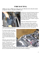
LEG/WHEEL ASSEMBLY
If not completed already, first
remove the bolts from the stainless
steel rod in preparation for
mounting the legs. With help from
an assistant, slide the Leg/Wheel
Assembly around the rear tire
(careful of the finish!), and align
the Leg Mounting Points (green)
with the slots in the Support Stand.
If available a very small amount of
‘Never Seize’ on the shaft is in
order here. Then start the stainless
steel shaft in from one side through
the tube on the support stand, and
through the first leg mounting point and its bushing. The fit is tight, so take your time.
Carefully work the shaft through the tube and the second leg mounting point. The shaft is
inserted properly when there it is inserted just past (approximately 1/8”) the end of the tube.
This distance should be about the same on both sides, but it is not critical as long as both sides
are inside the tube. If you need to, you can tap lightly on the shaft (brass drift is preferred here).
Once the shaft is in place, use a small amount of blue thread locker and install the (2) chrome
bolts and washers on the end of the shaft to finish it off. Make sure the legs move up and down
without any binding!
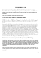
There is an optional step here. In order to allow the
legs to come up higher, we like to clearance the
plastic belt guard. The higher the legs come up, the
more clearance you will have in sharp turns. We used
an air saw to cut out this small notch. You can use
almost anything; the plastic is soft. Just raise the legs
by hand to determine how much to cut. If you give it
all the clearance it needs, the up stop of the legs will
be on the right side, not on the belt guard.
This change will have no negative effect on the belt
guards’ function.