
Product manual

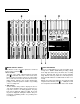


METER AND MONITOR SECTION
METER SELECT SWITCH
This switch is used to select the signal to be monitored
by the Peak Level Meters
Stereo Position:
The level of the signal output through the ST OUT
jacks is indicated. The meter on the far left shows
the level of the Left channel of the stereo signal, while
the second meter from the left shows the level of the
Right channel. Setting to this position during ping-
ponging or mixdown operations enables easy reading
of the recording level.
4 TRK Position:
Set the switch in this position to display the level of
each track. Starting from the far left, each meter cor-
responds to tracks 1–-4. During playback, the play-
back level is displayed; during recording, the record-
ing level is displayed. Setting the switch to this posi-
tion during overdubbing enables easy reading of the
recording level.
PEAK LEVEL METERS
There are 14 LED indicators in each meter which show
a range from - 20dB to +6dB. During recording, setting
levels high (but below the point where the recording
becomes distorted) will ensure the greatest dynamic
range with the lowest possible noise. An ideal point is
when the LED indicators for 0dB and above flash occa-
sionally.
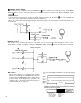
During stereo signal level indication, the actual specified
output from the ST OUT jacks is - 10dB (into a 50K
ohm load) when the LED indicators start to flash at 0dB.
10