
Reference Manual


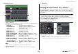


Table Of Contents
- How to Use This Reference Manual
- Contents
- Function Tree
- SELECTED CHANNEL section
- Channel Strip section
- Input and output patching
- Input channels
- Signal flow for input channels
- Specifying the channel name, icon, and channel color
- Making HA (Head Amp) settings
- Sending the signal from an input channel to the STEREO/MONO bus
- Sending a signal from an input channel to a MIX/ MATRIX bus
- Correcting delay between channels (Input Delay)
- Channel library operations
- OUTPUT channels
- Signal flow for output channels
- Specifying the channel name, icon, and channel color
- Sending signals from MIX channels to the STEREO/ MONO bus
- Sending signals from MIX channels and STEREO/ MONO channels to MATRIX buses
- Correcting delay between channels (Output Delay)
- Using the PORT TO PORT function
- Channel library operations
- EQ and Dynamics
- Channel Job
- Scene memory
- Monitor and Cue functions
- Talkback and Oscillator
- Meters
- Graphic EQ, effects, and Premium Rack
- I/O devices and external head amps
- MIDI
- Recorder
- Setup
- About the SETUP screen
- User settings
- Preferences
- USER DEFINED keys
- Functions that can be assigned to USER DEFINED keys
- USER DEFINED knobs
- Functions that can be assigned to USER DEFINED knobs
- Custom fader bank
- Console Lock
- Saving and loading setup data to and from a USB flash drive
- Word clock and slot settings
- Using cascade connections
- Basic settings for MIX buses and MATRIX buses
- Switching the entire phantom power supply on/ off
- Specifying the brightness of the touch screen, LEDs, channel name displays, and lamps
- Setting the date and time of the internal clock
- Setting the network address
- Setting up the Dante audio network
- Using GPI (General Purpose Interface)
- Help function
- Other functions
- Initializing the unit to factory default settings
- Adjusting the detection point of the touch screen (Calibration function)
- Adjusting the faders (Calibration function)
- Fine-tuning the input and output gain (Calibration function)
- Adjusting the LED color (Calibration function)
- Adjusting the brightness of the channel name display
- Adjusting the contrast of the channel name display
- Initializing the Dante audio network settings
- Warning/Error Messages
- Index
- Data List
- EQ Library List
- DYNAMICS Library List
- Dynamics Parameters
- Effect Type List
- Effects Parameters
- Premium Rack Processor Parameters
- Parameters that can be assigned to control changes
- NRPN parameter assignments
- Mixing parameter operation applicability
- MIDI Data Format
- Input/Output Specifications
- Electrical characteristics
- Mixer Basic Parameters
- Pin Assignment Chart
- MIDI Implementation Chart

Input and output patching
Reference Manual
17
PATCH/NAME screen
1 PATCH button
Indicates the port that is patched to the output channel. If you press this button when
another tab is active, a window will appear, enabling you to select the network and port.
2 Channel select button
Selects the channel to set.
NOTE
Switching channels on this screen will not affect the channel selection on the console.
3 Channel icon button
Indicates the icon and color that are currently selected for the corresponding channel.
When you press this button, a screen will appear in which you can select an icon or
sample name.
4 Channel number display box
Indicates the channel number. This item cannot be changed.
5 Channel name input box
Indicates the name that is assigned to the corresponding channel. When you press this
field, a keyboard window allowing you to assign a name will appear.
6 Category select list
Select the type of port.
7 Port select buttons
From the category, these buttons let you select the port to patch. To cancel the
selection, press the button once again.
8 Tabs
Enable you to switch between items.
9 Close button
Closes the screen.
Selecting the output channel for each output port
NOTE
If PATCH CONFIRMATION in the PREFERENCE tab on the USER SETUP screen is ON, a
confirmation dialog box will appear when you attempt to change the patch settings. If STEAL
PATCH CONFIRMATION is ON, a confirmation dialog box will appear when you attempt to
change a location that is already patched elsewhere.
3 54
1
9
6
7
2
8
STEP
1. In the Function Access Area, press the SETUP button.
2. Press the OUTPUT PORT button in the SYSTEM SETUP field located in the center of
the SETUP screen.
3. In the tabs below the OUTPUT PORT screen, select the output port you want to
control.
4. Press the channel select button of the port you want to operate.
5. Use the category select list and the channel select buttons to select the send-source
channel.
SETUP screen OUTPUT PORT screen