
Reference Manual


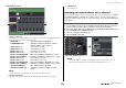


Table Of Contents
- How to Use This Reference Manual
- Contents
- Function Tree
- SELECTED CHANNEL section
- Channel Strip section
- Input and output patching
- Input channels
- Signal flow for input channels
- Specifying the channel name, icon, and channel color
- Making HA (Head Amp) settings
- Sending the signal from an input channel to the STEREO/MONO bus
- Sending a signal from an input channel to a MIX/ MATRIX bus
- Correcting delay between channels (Input Delay)
- Channel library operations
- OUTPUT channels
- Signal flow for output channels
- Specifying the channel name, icon, and channel color
- Sending signals from MIX channels to the STEREO/ MONO bus
- Sending signals from MIX channels and STEREO/ MONO channels to MATRIX buses
- Correcting delay between channels (Output Delay)
- Using the PORT TO PORT function
- Channel library operations
- EQ and Dynamics
- Channel Job
- Scene memory
- Monitor and Cue functions
- Talkback and Oscillator
- Meters
- Graphic EQ, effects, and Premium Rack
- I/O devices and external head amps
- MIDI
- Recorder
- Setup
- About the SETUP screen
- User settings
- Preferences
- USER DEFINED keys
- Functions that can be assigned to USER DEFINED keys
- USER DEFINED knobs
- Functions that can be assigned to USER DEFINED knobs
- Custom fader bank
- Console Lock
- Saving and loading setup data to and from a USB flash drive
- Word clock and slot settings
- Using cascade connections
- Basic settings for MIX buses and MATRIX buses
- Switching the entire phantom power supply on/ off
- Specifying the brightness of the touch screen, LEDs, channel name displays, and lamps
- Setting the date and time of the internal clock
- Setting the network address
- Setting up the Dante audio network
- Using GPI (General Purpose Interface)
- Help function
- Other functions
- Initializing the unit to factory default settings
- Adjusting the detection point of the touch screen (Calibration function)
- Adjusting the faders (Calibration function)
- Fine-tuning the input and output gain (Calibration function)
- Adjusting the LED color (Calibration function)
- Adjusting the brightness of the channel name display
- Adjusting the contrast of the channel name display
- Initializing the Dante audio network settings
- Warning/Error Messages
- Index
- Data List
- EQ Library List
- DYNAMICS Library List
- Dynamics Parameters
- Effect Type List
- Effects Parameters
- Premium Rack Processor Parameters
- Parameters that can be assigned to control changes
- NRPN parameter assignments
- Mixing parameter operation applicability
- MIDI Data Format
- Input/Output Specifications
- Electrical characteristics
- Mixer Basic Parameters
- Pin Assignment Chart
- MIDI Implementation Chart

Channel Strip section
Reference Manual
12
• If GAIN KNOB FUNCTION is set to DIGITAL GAIN, the DIGITAL GAIN knob will appear instead
of knob
1, and indicator 3 will not be displayed.
• You can also operate the digital gain by assigning INPUT GAIN DIGITAL GAIN to a USER
DEFINED knob, or by assigning an ALTERNATE function to a USER DEFINED key.
INPUT DELAY field (input channels only)
This field displays the delay status for the input channel. Press this field to open the INPUT
DELAY 8ch window.
1 DELAY ON/OFF indicator
Indicates the on/off status of the delay.
INSERT/DIRECT OUT field
This field displays the Insert/Direct out status. Press this field to open the INSERT 8ch
window.
1 INSERT ON/OFF indicator
Indicates the insert on/off status.
2 DIRECT OUT ON/OFF indicator (input channels only)
Indicates the Direct Out on/off status.
EQ field
This field graphically indicates the approximate response of
the EQ. Press this field to open the HPF/EQ 1ch window, in
which you can set the HPF and EQ.
NOTE
If DCA or monitor has been selected, this field will be blank.
DYNAMICS 1/2 field
This field displays the threshold value and meter for Dynamics
1/2. Press this field to open the DYNAMICS 1/2 1ch window.
NOTE
If DCA or monitor has been selected, this field will be blank.
SEND field
This field displays the send level, send on/off status, and pre/post
settings for 16 buses.
To select the 16 destination buses, use the [MIX/MATRIX] key in the
Fader Bank section.
Use the [TOUCH AND TURN] knob to adjust the send level for each bus.
Touch the knob of the bus you want to operate; it will be assigned to the
[TOUCH AND TURN] knob. If it is assigned to the [TOUCH AND TURN]
knob, touching that knob once again will display the SEND 8ch popup
screen.
This field varies depending on the type of the destination bus.
If the destination bus is VARI (mono):
The knob color and scale color indicate the send on/off and pre/post
status. If the send is off, the knob color turns gray. With the post setting,
the knob scale color turns gray.
If the slot is patched:
The slot name will appear.
If the rack is connected:
The patch and module name will appear.
If the output is connected:
Only the patch will appear.
1
1
2