
Owner's Manual


Page 16/63 GEO T RIGGING PROCEDURE
To be lifted in tension mode, the GEO T bumper requires either:
• one motor hoist and a bridle;
• or two motor hoists (easier initial angle setting);
In both cases, ensure that the motors are properly rated.
IMPORTANT
Motor hoists must be rated to support the entire cluster weight.
For arrays of 6 to 18 cabinets, 1 tonne motor hoists are sufficient.
Arrays of 18 cabinets and above should be supported with 2-tonne capacity motor
hoists.
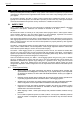
3.3.1 Front Kelping beam to bumper
• Disconnect Rear Beam from Front Beam by removing connecting axis. Store Rear Beam.
• Link the motor hoists to the Kelping Beam using front and rear upper axis (fixed beam), and
ensure that these axes are properly locked with the “R” clips supplied.
• Lift the Kelping Beam and position the bumper below it.
• Lower the Kelping beam so that the front beam load pin holes are aligned with the bumper load
pin holes (see drawing).
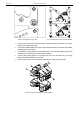
KELPING BEAM TO BUMPER SETUP
• Connect the Kelping Beam to the bumper with the two axes through the corresponding holes
(see drawing above) and ensure that these are properly locked with the “R” clips.
3.3.2
Bumper to first GEO T4805 assembly
4 push-pins (BLGEOT12-35, 12mm diameter x 35 mm length) connect the top GEO T4805 to the
bumper.
IMPORTANT
These 4 push-pins are slightly longer than the ones used to connect GEO T Array
modules (35mm length instead of 30mm).
Never use the GEO T 12mm x 30mm push-pins to connect the top GEO T4805 to the
bumper.