
Service manual


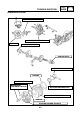

Table Of Contents

ELEC
SIGNALLING SYSTEM
7-21
3. The Master lights do not flash.
1. Bulb and bulb holder.
• Check the bulb and bulb holder for conti-
nuity.
CORRECTO
3.Voltage
• Connect the pocket tester (20 V DC) on the
bulb holder connector.
The circuit is in good condition.
CONTINUITY
2.Turning signal switch “b”
• Disconnect the handlebar switch coupler
(left) from the installation.
• Check the switch component for continuity
between “Brown/white” and “Chocolate
” and “Brown/White” and “Dark
green”
Cable (+) of tester
Green/Yellow
Cable (–) of tester
Black
• Place the main switch on “ON”.
• Activate the brake lever.
• Check if there is a voltage (12 V) on the
“Green/Yellow” cable of the bulb holder
connector.
SATISFIES THE
SPECIFIED VALUE
(12 V)
CORRECT
INCORRECT
The brake switch is defective, change.
OUTSIDE SPECIFIED VALUE
The connection circuit from the main switch
to the connector of the bulb holder is
defective, change.
NO CONTINUITY
Change the bulb and/or bulb holder.