
Service manual


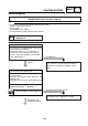


Table Of Contents

ELEC
LIGHTING SYSTEM
7-15
3. Connections
Check the connections throughout the ligh-
ting system.
See “ELECTRICAL DIAGRAM” section
CORRECT
The circuit is in good condition
CHECKING LIGHTING SYSTEM
1. The headlight does not light
1. Bulb and bulb holder
• Check the bulb and bulb holder to see if
there is continuity.
CONTINUITY
2. Voltage
• Connect the pocket tester (20 V AC) on the
headlight.
Headlamp light:
Cable (+) of
Yellow or Green
Cable (–) of tester
Black
A When the switch “k j”(intensity control)
is in position “k”.
B When the switch “k j” (intensity control)
is in position “j”.
• Place the main switch on “f”.
• Start the engine.
• Place the switch “k j” (dimmer switch) in
position “k” or “j”.
• Check if there is a voltage (12 V) in the
“Green” and “Yellow” cable in the connec-
tors of the bulb holder.
SATISFIES
THE SPECIFIED
VALUE (12 V)
The circuit is in good condition.
BAD CONNECTION
Correct
NO CONTINUITY
Replace the bulb and/or bulb holder.
OUTSIDE SPECIFIED VALUE
The connection circuit of the main switch to
the bulb holder connector is defective, repair
it.