
Specifications


ENG
R-123
1
2
ENGINE ASSEMBLY AND ADJUSTMENTS
4-51
ENGINE ASSEMBLY AND ADJUSTMENTS
WARNINGCAUTION:
Take care not to overtighten the Adjuster À and
remove the freeplay between both Push Rods.
• Hold the Adjuster to prevent it from moving and
tighten the Locknut to specification
• Tighten the Locknut ¿
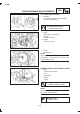
ææææææææææææææææææææææææææææææææææ
NOTE :
Tighten the Bolts in decreasing numerical order
(see number on the illustration)
13. Install :
• Kick Crank ¿
• Nut Kick Crank À
14. Install :
• Dowel Pins
• Gasket (Crankcase Cover #1)
New
• Crankcase Cover #1(L.H.)
NOTE:
Tighten the Bolts in decreasing numerical order.
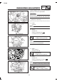
11. Install
• Strainer
NOTE :
Always keep its wider side, outside of Crankcase
12. Install :
• Dowel Pins
• Gasket (Crankcase #2)
New
• Crankcase Cover #2 (RH)
Bolts (Crankcase Cover):
10 Nm (1.0 m.kg, 7.2 ft.lb)
Nut (Kick Arm):
50 Nm (5.0 m.kg, 36 ft. lb)
Bolts (Crankcase Cover):
10 Nm ( 1.0 m.kg, 7.2 ft.lb)