
User Guide


16
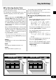
● Using the Foot Switch and the Bank
Switch
• Press a foot switch (1-3) to select the corre-
sponding patch number 1-3 in the currently se-
lected group/bank.
* If the Foot Switch’s function is set to “EFF” in the Utility
mode, it will not be possible to select a patch using the
Foot Switch. (See page 23)
• Press and hold the BANK switch until the dis-
play and the foot switch lamp flashes then re-
move your foot. In this condition, the following
procedure can be used.
* Even if the Foot Switch function is set to “EFF” in the
Utility Mode, this mode can be entered by stepping on the
BANK switch.
1. Hold Foot Switch 1 for more than one second to
switch between the USER AREA ↔ PRESET
AREA. When the area is changed, the Foot
Switch’s lamps will flash.
2. Hold Foot Switch 2 for more than one second to
decrease the group number by a value of one.
When the Group number is changed, the Foot
Switch’s lamps will flash.
3. Hold Foot Switch 3 for more than one second to
increase the group number by a value of one.
When the Group number is changed, the Foot
Switch’s lamps will flash.
4. Press a Foot Switch (1-3) to select the corre-
sponding bank number (1-3).
5. When a BANK is selected, the lamp in the dis-
play and foot switch lamp will flash quickly. Press
a Foot Switch (1-3) at this time to select the cor-
responding patch number (1-3).
* To cancel the selected patch, press the BANK switch. It will
return to the previous condition.
Using the DG-Stomp
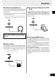
● Using MIDI Control
MIDI program change data transmitted from an ex-
ternal MIDI device such as the YAMAHA MIDI Foot
Controller MFC10, etc. can be used to select patches
in the DG-Stomp.
1. Use a MIDI cable to connect the MIDI IN jack on
the DG-Stomp to the MIDI OUT jack on an ex-
ternal MIDI device.
* Make sure to use a MIDI cable that conforms to the MIDI
standard. Also, limit the length of the MIDI cable to 15
meters. Use of a long cable may result in trouble such as
inferior performance of the device, etc.
2. Match the DG-Stomp’s MIDI receive channel with
the MIDI transmit channel on the external MIDI
device.
→ page 24 [Set the MIDI Receive Channel]
3. Create a Program Change Table*. (Factory de-
fault → Program Change No : Patch No. = 1:011,
2:012…128:4.12)
→ page 24 [Create a Program Change Table]
* This operation is used to assign patch numbers to a corre-
sponding program change number received from an exter-
nal device. For example, when the program change num-
ber “1” is received, the DG-Stomp’s patch number “113”
is recalled.
4. When program change data is transmitted from
an external MIDI device, the patch is selected
that corresponds to the program change table
you created.
* Refer to the owner’s manual for your external MIDI device
for instructions on how to transmit program change data.
MIDI IN
MIDI
OUT
MFC10, etc