
Owner's Manual
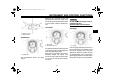


Table Of Contents
- XV19CTSV(C)/CTV(C)/CTMV Owner's Manual
- Introduction
- Table of Contents
- Safety Information
- Description
- Instrument and Control Functions
- Pre-Operation Checks
- Operation and Important Riding Points
- Periodic Maintenance and Minor Repair
- Owner's tool kit
- Periodic maintenance chart for the emission control system
- General maintenance and lubrication chart
- Checking the spark plugs
- Engine oil and oil filter cartridge
- Air filter element
- Checking the throttle cable free play
- Tires
- Clutch lever
- Checking the front and rear brake pads
- Drive belt slack
- Checking and lubricating the cables
- Checking and lubricating the brake and shift pedals
- Checking and lubricating the brake and clutch levers
- Lubricating the rear suspension
- Checking the front fork
- Checking the steering
- Checking the wheel bearings
- Battery
- Replacing the fuses
- Replacing a headlight bulb
- Replacing a turn signal light bulb
- Troubleshooting
- Motorcycle Care and Storage
- Specifications
- Consumer Information
- Index

INSTRUMENT AND CONTROL FUNCTIONS
3-6
3
Self-diagnosis devices
This model is equipped with a self-diag-
nosis device for various electrical cir-
cuits.
If any of those circuits are defective, the
engine trouble warning light will come
on, and then the odometer/tripme-
ter/clock display will indicate a two-digit
error code (e.g., 12, 13, 14).
If the odometer/tripmeter/clock display
indicates any error codes, note the
code number, and then have a Yamaha
dealer check the vehicle.
CAUTION:
ECA11590
If the display indicates an error
code, the vehicle should be checked
as soon as possible in order to avoid
engine damage.
Brightness control mode
The brightness can be adjusted for the
following:
● the multi-function meter unit panel
(item number “1”)
● the LCD (item number “2”)
● the speedometer, tachometer, and
the fuel gauge needles (item num-
ber “3”)
Select the brightness control mode as
follows.
1. Turn the key to “OFF”.
2. Push and hold the “SELECT”
switch.
3. Turn the key to “ON”, and then re-
lease the “SELECT” switch after
five seconds.
Item number “1” is displayed.
4. Adjust the multi-function meter unit
panel brightness level by pushing
the “RESET” switch.
5. Push the “SELECT” switch to se-
lect the LCD.
Item number “2” is displayed.
Adjust the LCD brightness level by
pushing the “RESET” switch.
1. Multi-function meter unit panel
2. LCD
3. Speedometer needle
4. Tachometer needle
5. Fuel gauge needle
1. Multi-function meter unit panel
2. Item number
3. Brightness level
U2C510E0.book Page 6 Monday, September 12, 2005 1:17 PM