
Operation Manual


Page 134 FT DX 9000MP OPERATION MANUAL
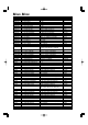
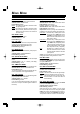
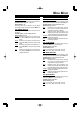
MENU MODE
DISPLAY GROUP
013. TFT COLOR
Function: Selects the TFT color.
Available Values: COOL BLUE/CONTRAST BLUE/
FLASH WHITE/CONTRAST UMBER/UMBER
Default Setting: COOL BLUE
014. DIMMER-METER
Function: Setting of the meter brightness level when
“DIM” is selected.
Available Values: 0 ~ 15
Default Setting: 4
015. DIMMER-VFD
Function: Setting of the frequency and TFT display
brightness level when “DIM” is selected.
Available Values: 0 ~ 15
Default Setting: 8
016. BAR DISPLAY SELECT
Function: Selects one of three parameters to be
viewed on the Tuning Offset Indicator.
Available Values: CLAR/CW TUNE/VRF-µTUNE/
NOTCH
Default Setting:CW TUNE
CLAR: Displays relative clarifier offset.
CW TUNE: Displays relative tuning offset between
the incoming signal and transmitted fre-
quency.
VRF-µTUNE: Displays the peak position of the VRF
or µTUNE filter.
NOTCH: While you rotate the NOTCH knob,
the center frequency of the IF NOTCH
feature will be indicated.
017. ROTATOR START UP
Function: Selects the starting point of your controller’s
indicator needle.
Available Values: 0/90/180/270º
Default Setting: 0º
018. ROTATOR OFFSET ADJ
Function: Adjusts the indicator needle precisely to
the starting point set in menu selection 123.
Available Values: –30 - 0
Default Setting: 0
019. RIGHT TX METER
Function: Selects the Sub meter function
Available Values: ALC/VDD
Default Setting: ALC
ALC: Indicates incoming signal strength on the sub
band (VFO-B) while receiving, and indicates the
ALC (Automatic Level Control) operating range
while transmitting.
VDD: Indicates the Vdd (final amplifier drain voltage)
at all times.
020. EXT DISPLAY
Function: This menu shold always be set to “DIS-
ABLE.”
Available Values: ENABLE/DISABLE
Default Setting: DISABLE