
Installation Guide


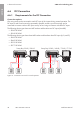


Table Of Contents
- Installation Manual
- Legal Provisions
- Table of Contents
- 1 Information on this Document
- 2 Safety
- 3 Scope of Delivery
- 4 Product Overview
- 5 Mounting
- 6 Electrical Connection
- 7 Commissioning
- 8 Disconnecting the Inverter from Voltage Sources
- 9 Decommissioning the Inverter
- 10 Technical Data
- 11 Compliance Information
- 12 Contact
- Instrucciones de instalación
- Disposiciones legales
- Índice
- 1 Indicaciones sobre este documento
- 2 Seguridad
- 3 Contenido de la entrega
- 4 Vista general del producto
- 5 Montaje
- 6 Conexión eléctrica
- 7 Puesta en marcha
- 8 Desconexión del inversor de la tensión
- 9 Puesta fuera de servicio del inversor
- 10 Datos técnicos
- 11 Información de cumplimiento
- 12 Contacto
- Instructions d’installation
- Dispositions légales
- Table des matières
- 1 Remarques relatives à ce document
- 2 Sécurité
- 3 Contenu de la livraison
- 4 Vue d’ensemble des produits
- 5 Montage
- 6 Raccordement électrique
- 7 Mise en service
- 8 Mise hors tension de l’onduleur
- 9 Mise hors service de l’onduleur
- 10 Caractéristiques techniques
- 11 Informations sur le respect des spécifications
- 12 Contact

6 Electrical Connection
SMA Solar Technology AG
Installation ManualSBxx-1SP-US-41-IA-xx-1044
11.
Connection of conductors of finely stranded wire
To connect conductors made of finely stranded wire, each terminal point must be opened.
• First insert the connector into the terminal point all the way to the lock (round
opening). Then insert a flat-blade screwdriver (blade: 3.2mm (
1
/
8
in)) as far as it
can go into the actuation shaft (rectangular opening). Hereby the lock opens and
the conductor can be placed into the terminal point as far as possible. After the
connection has been made, the flat-blade screwdriver must be pulled out of the
actuation shaft.
12.
WARNING
Fire hazard due to faulty conductor connection
If the conductors are inserted into the actuation shafts (right-angled openings), a fire may
occur during inverter commissioning.
13. Connect the conductors L and N to the terminal
block in accordance with the labeling. Insert each
conductor into the corresponding terminal point
(round opening) up to the stop.
AC-out
SPS
L N
14. Ensure the conductors are plugged into the terminal
points (round openings) as far at is will go and not
into the actuation shafts (rectangular openings).
AC-out
SPS
L N
AC-out
SPS
L N
15. Ensure that the terminal points are allocated to the correct conductors.
16. Ensure that the conductors are plugged completely into the terminal points up to their
insulation.
17. Install outlet in desired position (e.g. next to the inverter or as switch/outlet combination
optionally at short distance from the inverter (to max. 10m (393.7in))).
18. Connect the other end of the cable using it directly as energy supply to the outlet.
ENGLISH