
Installation Guide


REC Installation Manual - REC Alpha Series - UL 6
Rev A . Ref: NE
DRAINAGE HOLES
Each corner of the REC panel frame has small drainage holes spaced . in ( mm) from the corner of the panel frame that allow water caused by rain,
condensation, snow melt, cleaning or any other process to exit the frame easily and minimize damage caused by freezing and thawing (fig. ). These
holes must not be used for mounting the panel, and they must not be covered by any part of the mounting structure.
To enable effective drainage and ensure there is no damage to the panel, the drainage holes must remain fully open and enable water egress
during and aer installation.
The shape and dimensions of the drainage holes may vary slightly from the below image depending on product and/or frame design.
GROUNDING
A panel with exposed conductive parts is considered to be in compliance with UL & UL only when it is electrically grounded in accordance
with the instructions presented below and the requirements of the National Electrical Code. When grounding a panel, it must be done using an electrical
connection from the panel frame. Local regulations may require grounding of the panels. Where grounding is necessary or desired, it must be done using
an electrical connection from the panel frame. REC solar panels have a small round grounding hole positioned near each corner of the panel on both the
long side and the short side, as shown in fig. , to aid in grounding. These can be further identified by the grounding symbol stamped in the frame next to
it on the long side. The support bars across the rear of REC Alpha solar panels are connected to the frame via specially designed grounding clips and do
not need to be individually grounded. Check all applicable requirements before beginning installation. Grounding is achieved through securement to the
panel frame of the following UL Listed grounding Clips / Lugs in combination with the REC panel(s).
• Suitable grounding lugs must be used: Listed (KDER) ILSCO, GBL-DBT (tin plated) (E),
• Grounding cable size should be between AWG (. mm - . mm),
• Aach grounds to the grounding holes in the panel frames,
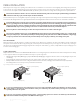
• Fix lug to the frame using a star washer (#) and lock nut (#), ensuring a conductive connection (fig. ),
• Follow the grounding device manufacturer’s installation instructions to ensure a safe and conductive connection, including any supplementary
hardware, e.g., star washer, and tighten according to recommended torque.
Fig. : Grounding lug dimensions and fastening torque for GBL-DBT
Cross section [AWG] Type Torque [in-lbs]
- Stranded
Stranded
- Stranded/Solid .
Where common grounding hardware (nuts, bolts, star washers, split-ring lock washers, flat washers and the like) are used to aach a
grounding device, the aachment must be made in conformance with the grounding device manufacturer’s instructions.
To avoid galvanic corrosion, galvanized or hot dipped zinc plated fasteners are preferred, however stainless steel fastening materials are
equally suitable.
Negative grounding of the panels is not required by REC.
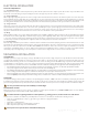
Fig. : Drainage and grounding holes
25.6- 0 [650 - 0 mm]
GR
GR
GR
GR
0-25.6 in [0 - 650 mm]
9.8 - 4 in
[250 - 100 mm]
4 - 9.8 in
[100 - 250 mm]
9.8 - 4 in
[250 - 100 mm]
4 - 9.8 in
[100 - 250 mm]
25.6- 0 [650 - 0 mm]0-25.6 in [0 - 650 mm]