
Installation Guide


EN-Rev IM/GN-AM-EN/A13 Copyright © November, 2018. Canadian Solar Inc.
4
|
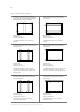
Table A
CS3U-P, CS3U-MS, CS6U-P and CS6U-M
Use four clamps on the long side. Mounting rails
run perpendicularly to the long side frame.
A1
A1 A1
A1
A1 range = (410 – 490) mm
Maximum Load:
Uplift load ≤ 3600 Pa
Downforce load ≤ 5400 Pa
A1 range = (340 – 550) mm
Maximum Load:
Uplift load ≤ 2400 Pa
Downforce load ≤ 2400 Pa
Min. 15 mm
overlap width
Clamp
Rail
Module frame
A1
A1
Use two clamps on the long side and two clamps
on the short side. Mounting rails run perpendicular
to the long side frame.
A1 range = (300 – 550) mm
A2 range = (200 – 250) mm
Maximum Load:
Uplift load ≤ 2400 Pa
Downforce load ≤ 2400 Pa
A2
A2