InstallatIon manual of stanDaRD solaR moDules for professional use only
| 1.0 GeneRal InfoRmatIon |3 1.0 GeneRal InfoRmatIon |3 1.1 InstallatIon manual DIsClaImeR |3 1.2 lImItatIon of lIaBIlItY |3 2.0 safetY PReCautIons |3 3.0 meCHanICal / eleCtRICal sPeCIfICatIons |4 4.0 unPaCKInG anD stoRaGe |5 5.0 moDule InstallatIon |6 5.1 moDule WIRInG |7 5.2 GRounDInG |9 6.0 mountInG InstRuCtIons |10 6.1 mountInG metHoD: BoltInG |11 7.0 maIntenanCe |14 amenDeD eDItIons anD Dates EN-Rev IM/GN-AM-EN/1.5 Copyright © November, 2018.
|3 1.0 GeneRal InfoRmatIon – bodily harm, injury or damage to property, in connection with handling PV modules, system installation, or compliance or non-compliance with This general manual provides important safety the instructions set forth in this manual. information relating to the installation, maintenance and handling of CS-series solar modules. Professional installer must read these guidelines 2.0 safetY PReCautIons carefully and strictly follow these instructions.
| When installing modules in light rain, · Do not artificially concentrate sunlight on a module. morning dew, take appropriate measures to prevent water ingress into the connector. · Do not connect or disconnect modules when current from the modules or an external source is present. Do not allow children or unauthorized persons near the installation site or storage area of modules. 3.0 meCHanICal / eleCtRICal sPeCIfICatIons · Do not install modules in strong wind.
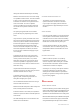
|5 Alternatively, a more accurate correction factor for modules under any circumstances. Localized heavy the open-circuit voltage can be calculated using the loads may cause severe micro-cracks at cell level, following formula: which in turn may compromise module reliability and void Canadian Solar Inc’s warranty.
| Inc. modules, provides the mounting system does · A nameplate is also affixed to the rear of each mo- not violate any other requirements of this manual. dule. This nameplate specifies the model type, as well as the main electrical and safety characteristics of the module. · Any mounting system limitations on inclination or accessories required to maintain a specific System Fire Class Rating should be clearly specified in the installation instructions and UL 2703 certification 5.
|7 damage the module mechanically or electrically. · Modules can be wired in series to increase voltage oPtImum oRIentatIon anD tIlt or in parallel to increase current. To connect modules in series, connect the cables from the positive · To maximize your annual yield, find out the terminal of one module to the negative terminal optimum orientation and tilt for PV modules of the next module. To connect in parallel, in your region.
| and proper actions should be taken to avoid dust and Canadian Solar Inc. offers optional cable moisture penetration inside the connectors. specifications to match various system configurations.
|9 CoRReCt ConneCtIon of PluG ConneCtoRs · Do not place connectors in locations where water could easily accumulate. · Make sure that all connections are safe and properly mated. The PV connector should not be subjected to stress from the exterior. Connectors should only be used to connect the circuit. They 5.2 GRounDInG should never be used to turn the circuit on and off. · For grounding requirements in North America, · Connectors are not waterproof when unmated.
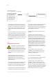
| GRounDInG metHoD: Bolt + tootHeD nut + CuP WasHeR. 1. To fix the wire between 2. Then tighten the bolt the flat washer and using the toothed nut. cup washer, place the cup washer (concave side up) between the frame and the wire.
| 11 · In cases where an additional support bar is correctly calculating the loads and ensuring that recommended to improve both mechanical the supporting structure meets all the applicable stability and long-term module performance, we requirements. recommend selecting a sufficiently resistant material. Canadian Solar Inc. recommends bars with a minimum thickness of 50 mm (1.97 in). mounting method: Bolting The support bar centerline should be positioned within 100 mm (3.
| table 3-1: approved bolting methods Bolting on short frame side using four standard mounting holes. Mounting rails run perpendicularly to the long frame side. An additional support bar should be placed below the module as shown below. Bolting on short frame side using four standard mounting holes. Mounting rails run parallel to the long frame side.
| 13 Bolting on long frame side using four innermost mounting holes. Mounting rails run perpendicularly to the long frame side. Maximum Load: Uplift load ≤ 2400 Pa Downforce load ≤ 5400 Pa Compatible module types: CS3L-P, CS1H-MS, CS1K-MS Notice: when the modules need to be installed in heavy snow area, please inform Canadian Solar Inc.’s technical support department in writing for advices. Failure to follow this notice may violate the warranty.
| 7.0 maIntenanCe · Do not make modifications to any components of the PV module (diode, junction box, plug connectors or others). · Regular maintenance is required to keep modules clear of snow, bird droppings, seeds, pollen, leaves, branches, dirt spots, and dust. · Modules with sufficient tilt (at least 15°), generally may not require cleaning (rain will have a selfcleaning effect).
InstallatIon manual anneX of stanDaRD solaR moDules for professional use only
2| anneX a: alteRnatIve mountInG metHoDs |3 mountInG metHoD a: ClamPInG |3 mountInG metHoD B: InseRtIon sYstems |17 mountInG metHoD C: CenteR mountInG metHoD WItH tHIRD PaRtY tRaCKeR |20 anneX B: alteRnatIve GRounDInG metHoDs |21 anneX C: meCHanICal anD eleCtRICal RatInGs |23 anneX D: moDule CleanInG GuIDelInes |30 amenDeD eDItIons anD Dates |31 InstallatIon manual DIsClaImeR The information contained in this manual is subject to change by Canadian Solar Inc. without prior notice.
|3 anneX a: alteRnatIve mountInG metHoDs All the basic requirements of the main installation for load calculations and for proper design of manual should apply to the alternative mounting support structure. methods, unless otherwise specified. · Canadian Solar Inc.’s warranty may be void in cases The loads described in this manual corresponds where improper clamps or unsuitable installation to test loads. For installations complying with IEC methods are found.
4| Clamp Rail Module frame Min. 15 mm overlap width table a Cs3u-P, Cs3u-ms, Cs6u-P and Cs6u-m a1 a1 a1 a2 a2 a1 a1 a1 Use four clamps on the long side. Mounting rails run perpendicularly to the long side frame. Use two clamps on the long side and two clamps on the short side. Mounting rails run perpendicular to the long side frame.
|5 a1 a1 a1 a2 a2 a2 a2 a1 Use four clamps on the long side. Mounting rails run parallel to the long side frame. Use four clamps on the short side and two clamps on the long side. An additional support bar should be placed below the center of the module.
6| Cs3K-P, Cs3K-ms, Cs6K-P, Cs6K-m, Cs6K-ms a1 a1 a1 a2 a2 a2 a2 a1 Use four clamps on the long side. Mounting rails run perpendicularly to the long side frame. Use four clamps on the short side. Mounting rails run parallel to the long side frame.
|7 a1 a1 a1 a1 a3 a4 a4 a5 a3 a4 a4 a5 Use four clamps on the long side. Mounting rails run parallel to the long side frame. Use six clamps on the long side. Mounting rails run perpendicularly to the long side frame. A1 range = (240 – 330) mm Maximum Load: Uplift load ≤ 2400 Pa Downforce load ≤ 4000 Pa A3 range = (80 –380) mm, A5 range = (80 –380) mm Maximum Load: Uplift load ≤ 4000 Pa Downforce load ≤ 6000 Pa a1 a2 a2 a1 Use two clamps on the long side and two clamps on the short side.
8| Cs3W-P a1 a1 a1 a1 Use four clamps on the long side. Mounting rails run perpendicularly to the long side frame. A1 range = (340 – 550) mm Maximum Load: Uplift load ≤ 2400 Pa Downforce load ≤ 2400 Pa A1 range = (410 – 490) mm Maximum Load: Uplift load ≤ 3600 Pa Downforce load ≤ 5400 Pa Cs3l-P a1 a1 a1 a1 a3 a4 a4 a5 a3 a4 a4 a5 Use four clamps on the long side. Mounting rails run perpendicularly to the long side frame. Use six clamps on the long side.
|9 Rail-less clamping for Cs3K-P, Cs3K-ms, Cs6K-P, Cs6K-m, Cs6K-ms Cantilever span span Cantilever support Rafter 24 inches (0.61 m) Clamp Interlock landscape installation, clamping on long side frame. Mounting Orientation Max Span Max Cantilever length Downforce Uplift 72 inches (1.83 m) 24 inches (0.61 m) 2200 Pa 1400 Pa 64 inches (1.63 m) 21.3 inches (0.54 m) 2400 Pa 1400 Pa 48 inches (1.22 m) 16 inches (0.41 m) 3400 Pa 1800 Pa 32 inches (0.81 m) 10.7 inches (0.
10 | Cs1K-ms, Cs1H-ms a1 a1 a3 a4 a4 a5 a1 a1 a3 a4 a4 a5 Use four clamps on the long side. Mounting rails run perpendicularly to the long side frame. Use six clamps on the long side. Mounting rails run perpendicularly to the long side frame.
| 11 Cs6a-P, Cs6a-m, Cs6vl-ms and Cs6a-ms a1 a1 a1 a2 a2 a2 a2 a1 Use four clamps on the long side. Mounting rails run perpendicularly to the long side frame. Use four clamps on the short side. Mounting rails run parallel to the long side frame.
12 | a1 a1 a3 a4 a4 a5 a1 a1 a3 a4 a4 a5 Use four clamps on the long side. Mounting rails run parallel to the long side frame. Use six clamps on the long side. Mounting rails run perpendicularly to the long side frame.
| 13 a2 a2 a2 a2 a2 a2 a2 a2 Use four clamps on the short side. Use four clamps on the short side and two clamps on the long side. An additional support bar should be placed below the center of the module. A2 range = (0 – 210) mm Maximum Load: Uplift load ≤ 2000 Pa Downforce load ≤ 2000 Pa A2 range = (170 – 210) mm Maximum Load: Uplift load ≤ 2400 Pa Downforce load ≤ 5400 Pa a1 a1 a3 a4 a4 a5 a1 a1 a3 a4 a4 a5 Use four clamps on the long side.
14 | Cs1v-ms a1 a1 a1 a2 a2 a2 a2 a1 Use four clamps on the long side. Mounting rails run perpendicularly to the long side frame. Use four clamps on the short side. Mounting rails run parallel to the long side frame.
| 15 a1 a1 a1 a1 Use four clamps on the long side. Mounting rails run parallel to the long side frame. A1 range = (240 – 330) mm Maximum Load: Uplift load ≤ 2400 Pa Downforce load ≤ 4000 Pa Cs1vl-ms, Cs1a-ms a1 a1 a1 a2 a2 a2 a2 a1 Use four clamps on the long side. Mounting rails run perpendicularly to the long side frame. Use four clamps on the short side. Mounting rails run parallel to the long side frame.
16 | a2 a2 a2 a2 a2 a2 a2 a2 Use four clamps on the short side. Use four clamps on the short side and two clamps on the long side. An additional support bar should be placed below the center of the module. A2 range = (0 – 250) mm Maximum Load: Uplift load ≤ 2400 Pa Downforce load ≤ 2400 Pa A2 range = (200 – 250) mm Maximum Load: Uplift load ≤ 2400 Pa Downforce load ≤ 5400 Pa a1 a1 a1 a1 Use four clamps on the long side. Mounting rails run parallel to the long side frame.
| 17 mountInG metHoD B: InseRtIon sYstems Do not bend the module frame. Do not touch the front glass or cast shadow onto it. · The mounting method has been qualified by Canadian Solar Inc. as well as certified by VDE and Do not damage the surface of the frame. CSA. Ensure that the insertion profiles overlap the module frame by at least 10 mm (0.39 in).
18 | Cs3K-P, Cs3K-ms, Cs6K-P, Cs6K-m, Cs6K-ms, Cs6v-P, Cs6v-m and Cs6v-ms Use two insertion profiles running parallel to the long side frame. Use two insertion profiles running perpendicularly to the long side frame. Maximum Load: Uplift load ≤ 2400 Pa Downforce load ≤ 4000 Pa Maximum Load: Uplift load ≤ 2000 Pa Downforce load ≤ 2000 Pa Use two insertion profiles running perpendicularly to the long side frame. An additional support bar should be placed below the module.
| 19 Use two insertion profiles running perpendicularly to the long side frame. An additional support bar should be placed below the module. Use two clamps on the support bar. Maximum Load: Uplift load ≤ 2400 Pa Downforce load ≤ 5400 Pa Cs1K-ms, Cs1H-ms Use two insertion profiles running parallel to the long side frame. Use two insertion profiles running perpendicularly to the long side frame. An additional support bar should be placed below the module. Use two clamps on the support bar.
20 | Use two insertion profiles running perpendicularly to the long side frame. An additional support bar should be placed below the module. Use two clamps on the support bar. Maximum Load: Uplift load ≤ 2400 Pa Downforce load ≤ 5400 Pa mountInG metHoD C: mountInG metHoDs WItH (sInGle-aXIs tRaCKeR) · Canadian Solar Inc. modules can be mounted on single-axis trackers using center clamps or mounting Mounting Rail holes as described below.
| 21 CS3W-P CS3U-P CS3W-P CS3U-P CS3W-P Arctech single-axis tracker Portrait two rows 3588 mm rail (bolting method / M8 bolt + M8 plain washer (O.D. = 24 mm) / 1155 mm holes position) Rail drawing No: CS2018007 Uplift load ≤ 2400 Pa Downforce load ≤ 2400 Pa SSMFIM-rev01 (SkySmart-Module Fixing Installation Manual) Soltec SF7 SingleAxis Tracker 2454 mm rail (Bolting method / M6 bolt + M6 plain washer (O.D.
22 | Company Grounding hardware Compatible mounting system Reference manual (version no.) Variety Lay-in-Lug + Star Washer (UL 2703 & UL 467 certified) Variety Related reference installation manual Schletter GmbH Schletter Rapid2+ Grounding Clamps Schletter Rapid2+ Schletter Rapid2+ Clamp installation instructions Array Technologies Inc. Grounding Strip ATI Duratrack HZ Solar Tracker (V3) DuraTrack™HZ Solar Tracker Installation Guide (January 2017, Rev. B-01) IronRidge Inc.
| 23 anneX C: meCHanICal anD eleCtRICal RatInGs Standard Test Conditions are: Irradiance of 1000 W/ ±10% or [0; +5 W] of the indicated values for Isc, m2, AM1.5 spectrum, and cell temperature of 25°C. Voc and Pmax. Specifications are subject to change The electrical characteristics are respectively within without notice.
24 | module type maximum operating operating Power voltage current Pmax vmp Imp open Circuit voltage voc short Circuit Current Isc max. series fuse Rating 15.00 Cs6v-255ms 255 27.2 9.38 33.3 9.91 Cs6vH-115ms 115 13.1 8.78 16.2 9.59 15.00 Cs6vH-120ms 120 13.3 9.03 16.4 9.67 15.00 Cs6vH-125ms 125 13.5 9.26 16.6 9.75 15.00 Cs6vl-150ms 150 19.5 7.7 24.6 9.11 15.00 Cs6vl-155ms 155 19.7 7.87 24.8 9.19 15.00 Cs6vl-160ms 160 19.9 8.
| 25 module type maximum operating operating Power voltage current Pmax vmp Imp open Circuit voltage voc short Circuit Current Isc max. series fuse Rating Cs6K-250m 250 30.4 8.22 37.5 8.74 15 Cs6K-255m 255 30.5 8.35 37.7 8.87 15 Cs6K-260m 260 30.7 8.48 37.8 8.99 15 Cs6K-265m 265 30.9 8.61 37.9 9.11 15 Cs6K-270m 270 31.1 8.67 38.2 9.19 15 Cs6K-275m 275 31.3 8.80 38.3 9.31 15 Cs6K-280m 280 31.5 8.89 38.5 9.43 15 Cs6K-285m 285 31.
26 | module type maximum operating operating Power voltage current Pmax vmp Imp open Circuit voltage voc short Circuit Current Isc max. series fuse Rating Cs6u-290m 290 36.3 8.00 44.7 8.51 15 Cs6u-295m 295 36.4 8.11 44.9 8.63 15 Cs6u-300m 300 36.5 8.22 45 8.74 15 Cs6u-305m 305 36.6 8.33 45.2 8.84 15 Cs6u-310m 310 36.7 8.44 45.3 8.95 15 Cs6u-315m 315 36.9 8.53 45.5 9.04 15 Cs6u-320m 320 37.2 8.61 45.6 9.13 15 Cs6u-325m 325 37.
| 27 module type maximum operating operating Power voltage current Pmax vmp Imp open Circuit voltage voc short Circuit Current Isc max. series fuse Rating Cs3K-280ms 280 31.7 8.84 38.5 9.49 30 Cs3K-285ms 285 31.9 8.94 38.7 9.57 30 Cs3K-290ms 290 32.1 9.04 38.9 9.65 30 Cs3K-295ms 295 32.3 9.14 39.1 9.73 30 Cs3K-300ms 300 32.5 9.24 39.3 9.82 30 Cs3K-305ms 305 32.7 9.33 39.5 9.9 30 Cs3K-310ms 310 32.9 9.43 39.7 9.
28 | module type maximum operating operating Power voltage current Pmax vmp Imp open Circuit voltage voc short Circuit Current Isc max. series fuse Rating Cs1vl-205ms 205 23.1 8.88 28.2 9.46 15 Cs1vl-210ms 210 23.3 9.01 28.4 9.58 15 Cs1vl-215ms 215 23.5 9.15 28.6 9.70 15 Cs1vl-220ms 220 23.7 9.28 28.8 9.82 15 Cs1vl-225ms 225 23.9 9.41 29.0 9.97 15 Cs1a-240ms 240 27.0 8.90 33.3 9.39 15 Cs1a-245ms 245 27.3 8.99 33.5 9.
| 29 module type maximum operating operating Power voltage current Pmax vmp Imp open Circuit voltage voc short Circuit Current Isc max. series fuse Rating Cs3W-410P 410 39.1 10.49 47.6 11.06 20 Cs3W-415P 415 39.3 10.56 47.8 11.14 20 Cs3W-420P 420 39.5 10.64 48.0 11.22 20 Cs3l-320P 320 31.8 10.07 38.8 10.66 20 Cs3l-325P 325 32.0 10.16 39.0 10.74 20 Cs3l-330P 330 32.2 10.24 39.2 10.82 20 Cs3l-335P 335 32.4 10.34 39.4 10.
30 | anneX D: moDule CleanInG GuIDelIne This manual covers requirements for the cleaning cleaning equipment. procedure of Canadian Solar Inc. photovoltaic modules. The purpose of these cleaning guidelines is to provide general information for cleaning · Do not use abrasive or electric cleaners on the module. Canadian Solar modules. Professional installers should read these guidelines carefully and strictly follow these instructions.
| 31 air. This technique can be applied as long as the method is efficient enough considering the existing conditions. method B: Wet cleaning If excessive soiling is present on the module surface, a non-conductive brush, sponge, or other mild agitating method may be used with caution. · Ensure that any brushes or agitating tools are constructed with non-conductive materials to minimize risk of electric shock and that they are not abrasive to the glass or the aluminum frame.