
Installation Manual

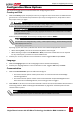


M o d u l e : 1 0 2 8 8 0 6 3 1 B
E n e r g y [ W h ] : 5 6 . 7
V d c _ O [ V ] : 4 0 . 0
V d c _ I [ V ] : 3 8 . 3
I _ i n [ A ] : 7 . 8
T e m p [ C ] : 2 8 . 0
l Module:Poweroptimizerserialnumber
l Energy:poweroptimizerenergy
l Vdc_O:Poweroptimizeroutputvoltage
l Vdc_I:Poweroptimizerinputvoltage(modulevoltage)
l I_in:Poweroptimizerinputcurrent
l Temp:Poweroptimizertemperature
ID Status
Thisscreendisplaystheinvertersoftwareversionandthecountrytowhichtheinverterisconfigured.
D S P 1 / 2 : 1 . 0 2 1 0 / 1 . 0 0 3 4
C P U : 0 0 0 3 . 1 9 x x
C o u n t r y : U S A 1
l ID:TheinverterID.
l DSP 1/2:TheDSPdigitalcontrolboardfirmwareversion
l CPU:Thecommunicationboardfirmwareversion
l Country:thecurrentcountrysetting
Server Communication Status
S e r v e r : L A N < S _ O K >
S t a t u s : < O K >
x x x x x x x x
< E R R O R M E S S A G E >
NOTE
If the connection method is CDMA (referred to as "Cellular" in the status screens) or GSM, the server
screen is replaced with the Cellular or GSM status screens (see Cellular Status on page 49 and
GSM Status on page 49).
l Server:ThemethodofconnectiontotheSolarEdgemonitoringplatform.
l S_OK:TheconnectiontotheSolarEdgemonitoringplatformissuccessful(shouldappearonlyiftheis
connectedtotheserver).
l Status:DisplaysOKiftheinverterestablishedsuccessfulconnectionandcommunicationwiththe
specifiedserverport/(LAN,RS485orZigBeePlug-in).
l xxxxxxxx:Eight-bitEthernetcommunicationconnectionstatus:Astringof1sand0sisdisplayed.1
indicatesOK,0indicatesanerror.
l Error message,accordingtofailure.RefertoErrorCodesonpage63.
IP Status
ThisscreendescribestheEthernetconfiguration:IP,Mask,GatewayandMACaddress(MediaAccess
Control)oftheInverter.
Chapter 5: Configuring the Inverter
Single Phase Inverter with HD-Wave Technology Installation MAN-01-00306-1.1
47