
Owner's Manual


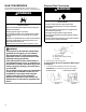


Table Of Contents
- RANGE SAFETY
- Range Safety
- RANGE MAINTENANCE AND CARE
- Self-Cleaning Cycle
- General Cleaning
- INSTALLATION INSTRUCTIONS
- REQUIREMENTS
- Tools and Parts
- Location Requirements
- Electrical Requirements (for Dual Fuel models) - U.S.A. Only
- Electrical Requirements (for Dual Fuel models) - Canada Only
- Electrical Requirements (for Gas models)
- Gas Supply Requirements
- INSTALLATION
- Unpack Range
- Install Anti-Tip Bracket
- Make Gas Connection
- Verify Anti-Tip Bracket Is Installed and Engaged
- Level Range
- Electronic Ignition System
- Complete Installation
- Remove Oven Doors
- Adjust Leveling Legs
- GAS CONVERSIONS
- Propane Gas Conversion
- Natural Gas Conversion
- Moving the Range
- SECURITE DE LA CUISINIERE
- Securite de la cuisiniere
- ENTRETIEN ET REPARATION DE LA CUISINIERE
- Programme d'autonettoyage
- Nettoyage general
- INSTRUCTIONS D'INSTALLATION
- SPECIFICATIONS
- Outils et pieces
- Exigences d'emplacement
- Specifications electriques (pour les modeles a double combustible) ± Etats-Unis seulement
- Specifications electriques (pour les modeles a double combustible) ± Canada seulement
- Specifications electriques (pour les modeles au gaz)
- Specifications de l'alimentation en gaz
- INSTALLATION
- Deballage de la cuisiniere
- Installation de la bride antibasculement
- Raccordement au gaz
- Verifier que la bride antibasculement est bien installee et engagee
- Reglage de l'aplomb de la cuisiniere
- Systeme d'allumage electronique
- Achever l'installation
- Retirer les portes du four
- Reglage des pieds de nivellement
- CONVERSIONS POUR CHANGEMENT DE GAZ
- Conversion pour l'alimentation au propane
- Conversion pour l'alimentation au gaz naturel
- Deplacement de la cuisiniere
- Blank Page
- Blank Page
- Blank Page
- Blank Page
- Blank Page

13
Install Anti-Tip Bracket
WARNING
Tip Over Hazard
A child or adult can tip the range and be killed.
Install anti-tip bracket to floor or wall per installation
instructions.
Slide range back so rear range foot is engaged in the
slot of the anti-tip bracket.
Re-engage anti-tip bracket if range is moved.
Do not operate range without anti-tip bracket installed
and engaged.
Failure to follow these instructions can result in death or
serious burns to children and adults.
1. Remove the anti-tip bracket that is taped inside the upper
oven with the package containing literature.
2. Determine which mounting method to use: floor or wall. If you
have a stone or masonry floor, you can use the wall mounting
method.
3. Determine and mark edge of range in the cutout space. The
mounting bracket can be installed on either the left side or
right side of the cutout. Position mounting bracket in cutout so
that right (or left) edge of the bracket is 15/16" (2.4 cm) from
the marked edge of the range, as shown.
A. Anti-tip bracket
B. Mark edge of range
C. 15/16" (2.4 cm)
4. Drill two 1/8" (3.0 mm) holes that correspond to the bracket
holes of the determined mounting method. See the following
illustrations.
Floor Mounting Wall Mounting
A. #12 x 1
5
/
8
" screws
B. Anti-tip bracket
A. #12 x 1
5
/
8
" screws
B. Anti-tip bracket
5. Using the two #12 x 1
5
⁄
8
" (4.1 cm) Phillips-head screws
provided, mount anti-tip bracket to the wall or floor.
Make Gas Connection
WARNING
Explosion Hazard
Use a new CSA International approved gas supply line.
Install a shut-off valve.
Securely tighten all gas connections.
If connected to propane, have a qualified person make
sure gas pressure does not exceed 14ʺ (36 cm) water
column.
Examples of a qualified person include: licensed heating
personnel, authorized gas company personnel, and
authorized service personnel.
Failure to do so can result in death, explosion, or fire.
Typical flexible connection
1. Apply pipe-joint compound made for use with propane gas to
the smaller thread ends of the flexible connector adapters
(see B and G in the following illustration).
2. Attach one adapter to the gas pressure regulator and the
other adapter to the gas shutoff valve. Tighten both adapters,
being certain not to move or turn the gas pressure regulator.