30" (76.2 CM) AND 36" (91.4 CM) RANGE HOOD Installation Instructions and Use & Care Guide For questions about features, operation/performance, parts, accessories or service, call: 1-800-253-1301 or visit our website at www.whirlpool.com In Canada, call 1-800-807-6777 or visit our website at www.whirlpool.
TABLE OF CONTENTS TABLE DES MATIÈRES RANGE HOOD SAFETY .................................................................2 INSTALLATION REQUIREMENTS ................................................4 Tools and Parts ............................................................................4 Location Requirements ................................................................4 Venting Requirements..................................................................5 Electrical Requirements ..................
IMPORTANT SAFETY INSTRUCTIONS WARNING: TO REDUCE THE RISK OF FIRE, ELECTRIC SHOCK, OR INJURY TO PERSONS, OBSERVE THE FOLLOWING: ■ Use this unit only in the manner intended by the manufacturer. If you have questions, contact the manufacturer. ■ Before servicing or cleaning the unit, switch power off at service panel and lock the service disconnecting means to prevent power from being switched on accidentally.
INSTALLATION REQUIREMENTS Tools and Parts Gather the required tools and parts before starting installation. Read and follow the instructions provided with any tools listed here. Tools needed ■ Drill ■ 1¹⁄₄" (3.0 cm) drill bit ■ ¹⁄₈" (3.
For the most efficient and quiet operation: Use no more than three 90° elbows. Installation Clearances ■ C ■ Make sure there is a minimum of 24" (61 cm) of straight vent between the elbows if more than 1 elbow is used. ■ Do not install 2 elbows together. ■ Use clamps or duct tape to seal all joints in the vent system. ■ The vent system must have a damper. ■ Use caulking to seal exterior wall or roof opening around the cap.
Calculating Vent System Length Electrical Requirements To calculate the length of the system you need, add the equivalent feet (meters) for each vent piece used in the system. 3¹⁄₄" x 10" (8.3 cm x 25.4 cm) Vent System Vent Piece 3¹⁄₄" x 10" (8.3 cm x 25.4 cm) 90° elbow 5.0 ft (1.5 m) 3¹⁄₄" x 10" (8.3 cm x 25.4 cm) flat elbow 12.0 ft (3.7 m) 3¹⁄₄" x 10" (8.3 cm x 25.4 cm) wall cap 0.0 ft (0.0 m) Observe all governing codes and ordinances.
INSTALLATION INSTRUCTIONS Prepare Location NOTE: It is recommended that the vent system be installed before hood is installed. Before making cutouts, make sure there is proper clearance within the ceiling or wall for exhaust vent. 1. Disconnect power. 2. Depending on your model, determine which venting method to use: roof or wall. 3. Select a flat surface for assembling the range hood. Place covering over that surface. 4. Lift the range hood and set it upside down onto covered surface. 5.
4. Repeat steps 1-3 for the underside of the top of the cabinet. Cabinet cutouts *¹⁄₂" (1.3 cm) To make a circular vent opening on the underside of the cabinet top: 1. Mark a centerline on the underside of the top of cabinet. 2. Mark a line 5" (12.7 cm) from the back wall on the underside of the top of cabinet. 3. Use a compass or a circle template to draw a circle with a diameter that is ¼" (0.64 cm) larger than the vent. 4. Use saber or keyhole saw to cut the circular vent opening.
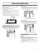
2. Lift the range hood up under cabinet and determine final location by centering beneath cabinet. Mark on the underside of cabinet the location of the 4 keyhole mounting slots on the range hood. Set range hood aside on a covered surface. NOTE: The 3¹⁄₄" x 10" (8.3 x 25.4 cm) rectangular vent connector can be installed up to 1" (2.5 cm) on either side of the hood center to accommodate off center ductwork. B A A C A. Keyhole slot D 3. Use ¹⁄₈" (3 mm) drill bit and drill 4 pilot holes as shown.
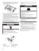
3. Remove the power supply knockout from the top or rear of the vent hood (depending on the incoming location of your home power supply cable) and install a UL listed or CSA approved ¹⁄₂" strain relief. 2. Use UL listed wire connectors and connect white wires (A) together. 3. Use UL listed wire connectors and connect black wires (B) together. WARNING A Fire Hazard Electrically ground the blower. A. Power supply knockout 4. Using 2 or more people, lift the hood into final position.
RANGE HOOD USE The range hood is designed to remove smoke, cooking vapors and odors from the cooktop area. For best results, start the hood before cooking and allow it to operate several minutes after the cooking is complete to clear all smoke and odors from the kitchen. The hood controls are located on the top of the range hood. To avoid damage to the stainless steel, do not use cleaners that contain chlorine. Cleaning Method: ■ Rub in direction of grain to avoid scratching or damaging the surface.
WIRING DIAGRAM Light Switch On - Off Motor Switch Low - Off - High SE116B BK R BR BK BK Speed 1 Speed 2 BK BK W R Ground Screw C19 N 12 W W Motor Characteristics Power Supply 120 VAC Frequency 60 Hz 0.9 ±10% A Amperage Wattage Rating 50 ±10% Watts Motor Resistance 22.3 ±10% Ohms White - Red 13.
ASSISTANCE OR SERVICE When calling for assistance or service, please know the purchase date and the complete model and serial number of your appliance. This information will help us to better respond to your request. If you need replacement parts If you need to order replacement parts, we recommend that you use only factory specified parts. Factory specified parts will fit right and work right because they are made with the same precision used to build every new appliance.
WHIRLPOOL CORPORATION MAJOR APPLIANCE WARRANTY LIMITED WARRANTY For one year from the date of purchase, when this major appliance is operated and maintained according to instructions attached to or furnished with the product, Whirlpool Corporation or Whirlpool Canada LP (hereafter “Whirlpool”) will pay for Factory Specified Parts and repair labor to correct defects in materials or workmanship. Service must be provided by a Whirlpool designated service company.
SÉCURITÉ DE LA HOTTE DE CUISINIÈRE Votre sécurité et celle des autres est très importante. Nous donnons de nombreux messages de sécurité importants dans ce manuel et sur votre appareil ménager. Assurez-vous de toujours lire tous les messages de sécurité et de vous y conformer. Voici le symbole d’alerte de sécurité. Ce symbole d’alerte de sécurité vous signale les dangers potentiels de décès et de blessures graves à vous et à d’autres.
IMPORTANTES INSTRUCTIONS DE SÉCURITÉ AVERTISSEMENT : POUR RÉDUIRE LE RISQUE D'INCENDIE, CHOC ÉLECTRIQUE OU DOMMAGES CORPORELS, RESPECTER LES INSTRUCTIONS SUIVANTES : ■ Utiliser cet appareil uniquement dans les applications envisagées par le fabricant. Pour toute question, contacter le fabricant.
EXIGENCES D'INSTALLATION Outils et pièces Exigences d'emplacement Rassembler les outils et pièces nécessaires avant d’entreprendre l’installation. Lire et observer les instructions fournies avec chacun des outils de la liste ci-dessous. IMPORTANT : Observer les dispositions de tous les codes et règlements en vigueur. ■ C’est à l’installateur qu’incombe la responsabilité de respecter les distances de séparation exigées, spécifiées sur la plaque signalétique de l’appareil.
Distances de dégagement à respecter ■ Ne pas installer 2 coudes successifs. ■ Au niveau de chaque jointure du circuit d'évacuation, assurer l'étanchéité avec les brides de serrage ou du ruban adhésif. ■ Le circuit d’évacuation doit comporter un clapet anti-reflux. ■ À l’aide d’un produit de calfeutrage, assurer l’étanchéité autour de la bouche de décharge à l’extérieur (à travers le mur ou le toit).
Calcul de la longueur du circuit d’évacuation Pour calculer la longueur effective du circuit d’évacuation nécessaire, additionner les longueurs équivalentes (en pieds ou mètres) de tous les composants utilisés dans le système.
INSTRUCTIONS D’INSTALLATION Préparation de l'emplacement REMARQUE : Il est recommandé d'installer le système d'évacuation avant de procéder à l'installation de la hotte. Avant d’exécuter les découpages, vérifier la disponibilité d’un dégagement suffisant dans le plafond ou le mur pour le conduit d’évacuation. 1. Déconnecter la source de courant électrique. 2. Selon le modèle, déterminer la méthode d’évacuation à utiliser : décharge à travers le mur ou le toit. 3.
4. Répéter les étapes 1 à 3 pour la face inférieure du sommet du placard. 3. Utiliser une scie sauteuse ou une scie à guichet pour découper l'ouverture rectangulaire pour le passage du conduit d'évacuation.
Installation du conduit d’évacuation 1. Installer le conduit d’évacuation à travers les ouvertures découpées dans le placard mural ou le mur. Achever l’installation du système d’évacuation conformément à la méthode d’évacuation sélectionnée. Voir la section “Exigences concernant l'évacuation”. 2. À l’aide d’un produit de calfeutrage, assurer l’étanchéité autour de la bouche de décharge à l’extérieur (à travers le mur ou le toit).
Installation du cordon d'alimentation Raccordement électrique 1. Pour les installations à raccordement direct, acheminer le câble d'alimentation du domicile selon les prescriptions du Code national de l’électricité ou des normes CSA et des codes et règlements locaux. La longueur du câblage depuis le tableau de distribution (avec fusibles ou disjoncteurs) doit être suffisante pour réaliser facilement le raccordement dans le boîtier de connexion de la hotte.
5. Installer le couvercle du boîtier de connexion. 6. Reconnecter la source de courant électrique. Achever l’installation 1. Installer l'ampoule à incandescence de 75 watts (maximum). Voir la section “Remplacement de l'ampoule à incandescence”. 2. Réinstaller le filtre à graisse s'il a été retiré. Voir la section “Entretien de la hotte”. 3. Contrôler le fonctionnement du ventilateur de la hotte et de la lampe. Voir la section “Utilisation de la hotte”.
Remplacement de l'ampoule à incandescence Éteindre la hotte et laisser l'ampoule refroidir. 1. Déconnecter la source de courant électrique. 2. Exercer une pression sur le cabochon en plastique de protection pour pouvoir le retirer de la hotte. A 3. Visser la lampe dans la douille. 4. Réinstaller le cabochon : exercer une pression sur le cabochon pour pouvoir insérer les pattes dans les ouvertures d’insertion. 5. Reconnecter la source de courant électrique.
ASSISTANCE OU SERVICE Lors d’un appel pour assistance ou service, veuillez connaître la date d’achat, le numéro de modèle et le numéro de série complets de l’appareil. Ces renseignements nous aideront à mieux répondre à votre demande. Si vous avez besoin de pièces de rechange Si vous avez besoin de commander des pièces de rechange, nous vous recommandons d’employer uniquement les pièces spécifiées par l’usine.
GARANTIE DES GROS APPAREILS MÉNAGERS WHIRLPOOL CORPORATION GARANTIE LIMITÉE Pendant un an à compter de la date d'achat, lorsque ce gros appareil ménager est utilisé et entretenu conformément aux instructions jointes à ou fournies avec le produit, Whirlpool Corporation ou Whirlpool Canada LP (ci-après désignées “Whirlpool”) paiera pour les pièces spécifiées par l'usine et la main-d'œuvre pour corriger les vices de matériaux ou de fabrication.
W10400321B © 2011. All rights reserved. Tous droits réservés. 5/11 Printed in Mexico. Imprimé au Mexique.