
Instruction for Use


GB
16
connection has been carried out, make sure that the
flexible metal pipe does not touch any moving parts and
is not compressed.
Only use pipes and seals that comply with current
national regulations.
Checking the tightness of the connection
When the installation process is complete, check the
pipe fittings for leaks using a soapy solution. Never use a
flame.
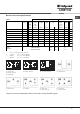
Adapting to different types of gas
To adapt the hob to a different type of gas other than
default type (indicated on the rating plate at the base of
the hob or on the packaging), the burner nozzles should
be replaced as follows:
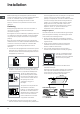
1. Remove the hob grids and slide the burners off their
seats.
2. Unscrew the nozzles using a 7 mm socket spanner, and
replace them with nozzles for the new type of gas (see
table 1 Burner and nozzle characteristics).
3. Reassemble the parts following the above procedure in
the reverse order.
4. Once this procedure is finished, replace the old rating
sticker with one indicating the new type of gas used.
Sticker are available from any of our Service Centres.
Replacing the nozzles on separate double flame
burners:
1. remove the grids and slide the burners from their
housings. The burner consists of 2 separate parts (see
figure);
2. unscrew the burers with a 7 mm wrench spanner. The
internal burner has a nozzle, the external burner has two
(of the same size). Replace the nozzle with models suited
to the new type of gas (see table 1).
3. replace all the components by repeating the steps in
reverse order.
Adjusting the burners primary air :
Does not require adjusting.
Setting the burners to minimum:
1. Turn the tap to the low flame position.
2. Remove the knob and adjust
the adjustment screw, which is
positioned in or next to the tap pin,
until the flame is small but steady.
3. Having adjusted the flame to the required low setting,
while the burner is alight, quickly change the position of
the knob from minimum to maximum and vice versa
several times, checking that the flame does not go out.
4. Some appliances have a safety device (thermocouple)
fitted. If the device fails to work when the burners are set
to the low flame setting, increase this low flame setting
using the adjusting screw.
5. Once the adjustment has been made, replace the seals
on the by-passes using sealing wax or a similar
substance.
If the appliance is connected to liquid gas, the regulation
screw must be fastened as tightly as possible.
Once this procedure is finished, replace the old rating
sticker with one indicating the new type of gas used.
Stickers are available from any of our Service Centres.
Should the gas pressure used be different (or vary slightly)
from the recommended pressure, a suitable pressure
regulator must be fitted to the inlet pipe (in order to comply
with current national regulations).
DATA PLATE
Electrical
connections
voltage of 220-240V ~ 50/60Hz
voltage of 220-230V ~ 50/60Hz
maximum power absorbed 2000W
(see data plate )
This appliance conforms to the
following European Economic
Community directives:
-73/23/EEC dated 19/02/73 (Low
Voltage) and subsequent
amendments
- 89/336/EEC dated 03/05/89
(Electromagnetic Compatibility)
and subsequent amendments
- 93/68/EEC dated 22/07/93 and
subsequent amendments.
- 90/336/EEC dated 29/06/90 (Gas)
and subsequent amendments.
- 2002/96/EC