Customer Service TM Washer Service Manual 16010061 Compiled From 16008373, 16010199, 16010886 11/03
SAFETY PRECAUTIONS This manual is to be used only by a Maytag Authorized Service Technician familiar with and knowledgeable of proper safety and servicing procedures and possessing high quality testing equipment associated with microwaves, gas, and electrical appliance repair. All individuals who attempt repairs by improper means or adjustment subject themselves and others to the risk of serious or fatal injury. USE ONLY GENUINE MAYTAG APPROVED FACTORY REPLACEMENT COMPONENTS.
INTRODUCTION Each model will be covered separately in a section pertaining only to its control system and internal components. Because the basic structure for all washers is the same, they will be covered generally without regard to model. Model(s) covered in this manual: MAH3000 For additional information on material covered in this manual, including safety issues, contact: Maytag Appliances Sales Company 240 Edwards Street, S.E. Cleveland, TN 37311 Phone: 423.472.3333 FAX: 423.478.
CONTENTS I N T R O D U C T I O N ........................................................................................................................................................... i C O N T E N T S ....................................................................................................................................................................... i i SECTION 1. G E N E R A L I N F O R M A T I O N ......................................................................................
SECTION 3. T R O U B L E S H O O T I N G ................................................................................................................ 3 - 1 DIAGNOSTIC FLOW CHARTS....................................................................................................3-4 Fills and Will Not Tumble ................................................................................................................................... 3-4 Washer Overfills ...............................................
SEAL SYSTEM .................................................................................................................................................................. 7-6 OUTER TUB ASSEMBLY ............................................................................................................................................ 7-7 B E A R I N G S .........................................................................................................................................................
SECTION 1. GENERAL INFORMATION PRE-INSTALLATION REQUIREMENTS NOTE: Proper installation is the responsibility of the purchaser. cause an extended fill time. Refer to the troubleshooting section for more information regarding a solution for slow fill situations. Checkpoints for proper installation: • Properly grounded electrical outlet is required. Use 15 amp fuse or compatible circuit breaker for electrical service. • Standpipe Drain System must accept 1½" O.D. drain hose.
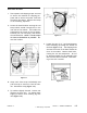
INSTALLATION 1. Two separate red shipping straps are used to secure the machine for shipping purposes and to secure the power cord with the water inlet hoses. Remove the straps in the following sequence: A. Locate the metal buckles securing the red straps which extend through slots in the rear wall of the cabinet. The buckles are positioned in the center of the red straps. Carefully cut the red straps, and remove the metal buckles. NOTE: Cut the straps as close to the buckles as possible.
Turn on the water and check for leaks (Figure 1-5). Note the H and C designations on the water valve bracket for the Hot and Cold hoses. Figure 1-4 4. Figure 1-5 Slide the washer into position and check the levelness and stability of the washer. If necessary, slide the washer out of position to either raise or lower the leveling leg as required to level and stabilize the washer securely on all four legs. Slide the washer back into position to confirm levelness to the floor.
Plug power cord into a properly grounded 120 volt AC-approved electrical service. This must be protected by a dedicated 15 amp fuse or circuit breaker. All grounding and wiring should be performed in accordance with national and local codes. USE OF ADAPTERS IS NOT RECOMMENDED. Figure 1-6 SPECIFICATIONS CAPACITY 3.1 Cubic Feet ELECTRICAL 120 volts, 60 Hz; Requir es 15 amp circuit br eaker or fused electrical supply . Power cord must be connected to a properly grounded and polarized outlet.
WASHER CONTROLS The control system in the Neptune horizontal axis washer generally consists of a timer and microprocessor-based machine control. These receive input signals and send output signals to other equipment in the washer, including the motor and motor control, user input switches, user indicator lights, the door latch and lock assembly, water valves, drain pump, unbalance switches, dispenser actuator wax motors, a pressure switch, and a tub light.
Series 17 & Later Figure 1-8 INPUT DEFINITIONS DOOR LOCK SWITCH INPUT When input is present, this is indication the washer door is locked. The machine controller will not command the spinner to spin faster than 50 rpm when the input is not present prior to spin. END-OF-CYCLE SIGNAL INPUT The End-of-Cycle Signal Input is energized through a user input switch on the control panel.
machine control interprets this loss of power as an indication that the water level has reached the full level. When the washer is at the "full" level and the timer is set in a Prewash Tumble, Main Wash Tumble, Light Wash Tumble, or Rinse Tumble increment, the machine control will begin the sequence timing defined for each cycle and fabric selection setting (See Cycle Sequence Definitions).
OUTPUT DEFINITIONS DOOR LOCKED LIGHT OUTPUT NOTE: This section applies only to washers between Series 10 and 16. The "Door Locked" lights on washers from Series 17 and after are controlled by a "Door Locked" light switch. The Door Locked Light Output signal powers a 1/3 watt neon indicator lamp on the control panel. This output is first energized when the Door Lock Wax Motor Output is energized. At the end of the cycle, it remains energized for 50 seconds after the Door Lock Switch Input shuts down.
The machine control counts the number of rinses during a normal wash cycle. In the first and second Rinse Tumble increments, the machine control will energize the Timer Motor Output as soon as the Pressure Switch Input is no longer energized, indicating that the water has reached the full level. In the third and fourth (if Extra Rinse is selected) Rinse Tumble increments, the machine control will energize the Timer Motor Output 30 seconds after the Pressure Switch Input is no longer asserted.
CYCLE SEQUENCE DEFINITIONS NOTE: Refer to Section 2: Timer Input Charts for information on the timing of each cycle sequence. BLEACH DISPENSE In a Bleach Dispense increment, the machine control will follow the same tumble pattern and speed as in a Main Wash Tumble increment. D E L AY During a Delay increment, the door Lock Wax Motor Output, Door Locked Light Output (Series 17 and later only), Motor Torque Output, "On" light (Series 10 to 16 only), and Water Valve Outputs are de-energized.
In a Prewash Tumble increment, the machine control will de-energize the line relay if the washer continues to tumble for 15 minutes. This would only occur if the timer were to stall (See Section 1: Timer Motor Output and Section 2: Timer Input Chart). MISCELLANEOUS Door Latch Switch Monitoring At the end of a cycle, when the timer advances into the Idle increment, the machine control will keep the line relay energized until it loses power when the door latch switch opens.
The following rules determine the maximum number of redistribution attempts that will be allowed in each spin step before the machine control skips the step and continues with the spin profile (See Section 2: Unbalance Control System). STOPPING THE WASHER 1. With the washer running, power is supplied to the machine control and washer from gray wire no. 26 through the line relay. 2. When the user presses the push-to-start button, a signal is sent to the machine control through red wire no.
CYCLE REVIEW Main Wash Time/Total Cycle Time - Minutes (See Notes). N on- M ax Ex t ra c t C ot t on/ S t urdy E a sy C a r e / Pe rm Press D e lic a t e s H a nd W a sh a b l e s H e a v y W a sh 2 3 .0 /4 9 . 0 2 0 .0 /4 5 . 5 20 /46.5 N o t A p p lic ab le N o r m a l W a sh 1 7 .0 /4 3 . 0 1 4 .0 /3 9 . 5 1 4 .0 /4 0 . 5 N o t A p p lic ab le Lig h t/ Q u ic k W as h 1 1 .0 /3 7 . 0 8 . 0 / 3 3 .5 7 . 0 / 3 4 .5 N o t A p p lic ab le Fi n a l S p i n (R PM / M i n ) 80 0/3.
GENERAL COMPONENT EXPLODED VIEW 16008373-01 © 1998 Maytag Corporation SECTION 1.
SECTION 2. ELECTRICAL ELECTRICAL COMPONENTS & TESTING TEST EQUIPMENT The equipment required to service Maytag products depends largely upon the conditions you encounter. Locating a malfunction will Description Part Number Analog Test Meter 20000005 Digital Test Meter 20001001 Clamp-On 20000002 Ammeter AC Voltage Sensor 20000081 Analog Test Meter can be used to check for open or closed circuits, measure resistance, AC and DC volts, and temperature.
ELECTRICAL TESTS Water Valve Test Warning - Always shut off electrical power to the unit before beginning any service repair procedures. Grounded Components When performing service diagnostics, replacements and repairs, always check to determine whether all ground wires linking panel and components are reattached if removed. Voltage Checks Generally, these checks will consist of taking readings at the wall receptacle to determine the availability of voltage to the product.
Timer & Console Switches T C B The timer is located in the control console on the back. It is composed of a series of switches driven by an electric timer motor. The timer motor rotates a pinion gear which then rotates internal cams. As the cams rotate, they lift and drop various switch contacts which ride on the cam. The internal switches provide cycle sequence or step inputs to the machine control to control the pump, dispenser wax motors, delay light, ON light and timer motor.
Software in the machine control board specifically monitors the timer input circuits to determine where the timer is in all the wash cycles and will rapidly advance the timer to OPEN and break contacts in the timer. The timer is solely used as an off-board set of relay switches. Note: The timer motor is hard wired to timer cams 10T and 10B in the timer.
Machine Control The machine control microprocessor board is located in the control console, mounted to the rear panel. The board receives input from the timer, door latch and lock switches, and unbalance and selector switches on the console. It also communicates with the motor control board to facilitate the various cycles and drive the motor for optimum performance. Torque and speed of the motor are monitored through the motor control board.
M A C H IN E CON TROL BOARD T ERM IN A L/ W IRE M A C H IN E CON TROL BOARD T ERM IN A L/ W IRE V O L T A G EAPP R O X .
DRIVE MOTOR The drive motor is a switched reluctance type motor. The basic operating principle of the switched reluctance motor is direct magnetic attraction between the stationary electromagnetic coils (stator) and a specially configured rotor or armature (Figure 2-4). The rotor is comprised of stacked plates or laminations mounted on a center shaft. The shape of these laminations are characteristic of the switched reluctance motor.
Motor & Motor Contr ol TTest est Control 1. Set the timer knob into the delay increments. 2. Press the push-to-start switch to start the washer in the delay mode. Confirm the delay light is ON. 3. Check for 120 VAC between the L and N terminals (black wire no.27 and white wire no. 13) on the motor control board. If not present, check wiring between the machine control and the motor control boards. 4. Unplug the washer power cord. Test cord to the same board terminals. 5.
To gain access to the motor control board terminals (Figure 2-6): 1 . Disconnect power to the washer prior to testing. 2 . Remove the two screws securing the motor control assembly to the base. Unsnap the two twist-lock wire ties restraining the motor to the motor control board harness base. windings check (See Motor Windings Check). 10. Check Phase B by disconnecting the white or red wire at the motor control board.
PHASE WIRE COLORS MOTOR CONDITION RESULT/SOLUTION C Yellow or Orange Runs -Phases A&B are operating correctly. (Check Phase A and B) -Phase A or B is non-functional. (See Step 10) Does Not Run B White or Red Runs Does Not Run A Black or Blue Runs Does Not Run -Phases A&C are operating correctly. (Check Phase A and C) -Phase A or C is non-functional. (See Step 10) -Phases B&C are operating correctly. (Check Phase B and C) -Phase B or C is non-functional.
The following table indicates voltage checks of the tachometer harness between the motor and motor control board. Figure 2-11 The motor control monitors the signals and communicates this information to the machine control. The purpose of this signal is to tell the motor when to energize each winding in the motor and to tell the machine control the actual motor speed.
Whenever a displacement switch is tripped, the machine stops and redistributes the clothes load. This involves a three (3) second pause, followed by a five (5) second reverse tumble (47-49 rpm) to redistribute the clothes load. The washer will pause again for three (3) seconds, then start the distribution profile again. To redistribute the load, the machine tumbles the load (50-90 rpm) and again attempts to pass through critical (about 150 rpm).
Inertial Unbalance Switch The inertial unbalance switch is located on the upper right hand side of the outer tub, in front of the top concrete weight. The switch consists of a moving weight in the switch body which presses against the switch contacts. If the unbalance of the outer tub becomes too erratic, the moving weight will open the contacts in the switch.
16008373-01 SECTION 2.
SECTION 3. TROUBLESHOOTING Warning - Always shut off electrical power to the unit before beginning any service repair procedures. Shuts OFF When Push-To-Start Button Released: Check for proper wiring of BK 27 to COMM and GY 26 to NO. If reversed, the washer will shut off when button is released. If wiring is proper, replace machine control board. Line relay may be bad (See Section 1: Push-ToStart Line Relay Operation).
Tumbles Only: Excessive Vibration: When the door lock mechanism is in the "locked" mode, the wax motor has extended, forcing the latch axle to engage the door lock enable switch. This ensures the door is fully locked and the switch can then complete the signal back to the machine control board indicating the door is locked. Check connector P3(7)/YL 36 wire to verify if the terminal is making good contact to the board terminal. Check the door lock enable switch for continuity when the button is depressed.
Door Leaks: Dispenser Does Not Dispense Dispense:: Usually this occurs when the door is remounted into the shroud and the technician fully tightens the top hinge screw prior to inserting the lower screw. The technician should fully seat the door into the shroud evenly prior to tightening the hinge bracket screw into the shroud. Check also for excess plastic flashing in the tab area of the plastic shroud. Carefully remove the excess flash and remount the boot gasket.
TROUBLESHOOTING 16008373-01 SECTION 3.
TROUBLESHOOTING 16008373-01 SECTION 3.
TROUBLESHOOTING 16008373-01 SECTION 3.
TROUBLESHOOTING 16008373-01 SECTION 3.
TROUBLESHOOTING 16008373-01 SECTION 3.
TROUBLESHOOTING 16008373-01 SECTION 3.
TROUBLESHOOTING 16008373-01 SECTION 3.
TROUBLESHOOTING 16008373-01 SECTION 3.
TROUBLESHOOTING 16008373-01 SECTION 3.
TROUBLESHOOTING Use a knife or scissors to cut across the + in the center of the dial and press the template over the timer shaft. Align the template with the OFF indicators of the Quick Wash and Regular wash on the facia. Press the timer knob onto the timer shaft. 16008373-01 SECTION 3.
MISCELLANEOUS INFORMATION Energy Usage: The energy usage averages up to 0.10 Kwh per cycle, when using the Regular cycle with Normal wash. Peak amperage is 7.5 amps during acceleration to high speed spin, with nominal running amperage at a maximum of 5.0 amps.
SECTION 4. CONSOLE Warning - Always shut off electrical power to the unit before beginning any service procedure. 5 . Push the bottom of the console toward the back panel to disengage the six locking feet from the top cover (Figure 4-3) 4-3). REMOVAL 1 . Disconnect power to the unit. 2 . Remove the three screws securing the console rear cover plate across the rear top edge of the console (Figure 4-1) 4-1).. Console Mounting Screws Figure 4-3 6 .
VERTICAL SWITCHES (Push Button) HORIZONTAL SWITCHES (Push-to-Start) REMOVAL REMOVAL Depress the tab at the top of the switch with a screwdriver to disengage the tab from the console. Pivot the switch away from the console to remove (Figure 4-5) 4-5). Depress the locking tab on the switch to disengage it from the locking tab on the console. Pivot the switch from the console (Figure 4-6). REPLACEMENT REPLACEMENT Align the rib on the bottom of the switch with the slot in the console.
TIMER REMOVAL 1 . Disconnect power to the unit. REPLACEMENT 2 . Carefully lift the timer knob and dial off the timer shaft by pulling the knob away from the face of the control console (Figure 4-7). 1 . Align the three tabs of the timer into the slots of the console. 2 . Insert the timer into the slots and slightly lift the locking tab of the timer. Slide the timer away from the endcap until the locking tab can engage with the square hole in the console. 3 . Replace mounting screw. Figure 4-7 3 .
16008373-01 SECTION 4.
SECTION 5. CABINET ASSEMBLY Warning - Always shut off electrical power to the unit before beginning any service repair procedures. DOOR ASSEMBLY & HINGES The door assembly is reversible. It contains an inertial vibration damper comprised of a steel plate suspended with springs. The damper is designed to tune out excessive vibrations generated by the machine during the spin cycle. Replacement inner door liners are shipped with the vibration damper in place. Figure 5-1 REVERSAL 1.
Cabinet Vibration Absorber The purpose of the cabinet vibration absorber is to provide a dampening effect to the washer during the spin cycle. By dampening the machine vibration, the washer is able to maintain and achieve optimum spin performance. The stabilizer is attached to the inner door plug with two screws. 2. Open the door and remove the four screws along the inside lip of the door opening.
TOP COVER DOOR LOCK MECHANISM REMOVAL 1. Remove the front panel (See Front Panel Removal). 2. Remove the four screws fastening the dispenser bezel to the top of the top cover (See Dispenser Assembly). 3. Remove two 5/16" hex head screws securing the two hold down brackets on the top cover (Figure 5-5). 4. To remove the hold down brackets, swing the bracket to the outside to unhook the bracket from the slot in the top cover lip (Figure 5-6). 5.
Two switches in the door lock mechanism inform the machine microprocessor control when the door is latched shut and when the door is securely locked. For more information, refer to section on Electrical-Mechanical Troubleshooting. An emergency access cord (filament) is attached to the sliding gear, should the wax motor fail in the extended position and entry into the washer is necessary. To gain access to the cable, removal of the dispenser bezel is necessary. Once removed, the cable is exposed.
CABINET ASSEMBLY w/REAR ACCESS PANEL Removal of the access panel gains access to the rear components of the washer (Figure 5-11). Figure 5-9 3. Remove the door (See Door Assembly and Hinge Removal). 4. Removal and replacement of the screws in the following order, as illustrated, is necessary to provide proper alignment of the parts. Failure to do so will hinder removal and replacement of the shroud onto the cabinet (Figure 5-10).
16008373-01 SECTION 5.
SECTION 6. WATER-CARRYING COMPONENTS Warning - Always shut off electrical power to the unit before beginning any service repair procedures. WATER VALVE 5. While pulling the bracket away from the cabinet, rotate the left side of the bracket away from the washer. 6. Remove the wire harness from the water valve coils (Blue & White wires - Cold; Orange & White wires - Hot) and remove the clamp from the injector hose. 7. Remove two 5/16" hex head screws securing the valve to the mounting bracket.
WATER LEVEL PRESSURE SWITCH The water pressure switch is located in the console area and mounted to a galvanized bracket secured to the rear panel of the console. The air dome hose is inserted into the lower end of the mounting bracket (Figure 6-2). The nipple of the pressure switch is inserted into the end of the air dome hose which is secured by the lower mounting bracket. Bracket Pressure Switch A) Slide Switch Off 7. To replace, insert air dome hose into the bracket.
5. Pull the air dome and hose out through the sump opening in the spin basket (Figure 6-3). 5. Remove all slack in the hose between the upper and lower clips holding the air dome hose. This reduces the potential for noise. REPLACEMENT/ROUTING 6. Route the air dome hose into the center rear hole in the top cover. Route toward the pressure switch and secure the hose to the pressure switch. 1. Thread the narrow end of the hose through the air dome outlet in the rear of the outer tub (Figure 6-3).
4. Remove the front panel and top cover (See Front Panel & Top Cover Removal). 5. Disconnect the hoses attached to the dispenser assembly. 6. While lifting, rotate the dispenser assembly 90 degrees in a counterclockwise direction. NOTE: The two tabs on the side wall of the dispenser bottom may break off if the above procedure is not followed properly. 5. Remove the hose clamp and injector hose from the spout on the front upper area of the outer tub. 6.
Figure 6-6 Figure 6-7 CLEANING THE PUMP The pump assembly can also be disassembled without removing the hoses from the pump (See Figure 6-6). 1. Depress the locking tab on the face of the pump housing. 2. Rotate the block portion of the pump containing the motor windings toward the front of the washer. This will disengage the locking tabs of the pump housing from the pump face. 4. Position the second pump near the first pump and connect the accessory connector to the sump intake of the second pump.
DRAIN HOSE The drain hose attaches to the pump and is routed through the lower rear wall of the cabinet. The drain hose is protected externally by a shield. Drain Hose Access Cover REMOVAL 1. Disconnect power to the unit. Figure 6-9 2. Remove the four ¼" hex head screws securing the access panel to the rear wall of the cabinet. 3. Remove the ¼" hex head screw securing the drain hose shield. Remove shield. 4.
16008373-01 SECTION 6.
SECTION 7. OUTER TUB & SPINNER ASSEMBLY Warning - Always shut off electrical power to the unit before beginning any service repair procedures. REMOVAL 1. Disconnect power to the unit. 2. Remove the front panel, top cover and front shroud (See Front Panel, Top and Front Shroud Removal). BAFFLES The baffles in the spin basket distribute and redistribute the clothes during the tumbling action of the washer. REMOVAL 3.
6. Unsnap the locking tabs of the door boot around the inside perimeter of the door shroud (Figure 7-1). REPLACEMENT 1. Align the door boot with the D-shape toward the front, with the flat of the D toward the bottom. Also, locate the large tab toward the top center of the shroud. 2. Stretch the rear lip of the door boot onto the tub cover. 3. Move the rear door boot lip along the face of the tub cover until the locator notches in the door boot align with the locator ribs in the tub cover.
REMOVAL 1. Disconnect power to the unit. 2. Remove the front panel, top cover, front shroud, outer tub cover and rear baffles (See Front Panel, Top cover, Front Shroud, Outer Tub Cover and Rear Baffle Removal). 3. To separate the spinner tub support from the spinner, remove the three rear baffles within the spin basket by removing the two screws securing each baffle (See Baffle Removal).
Profile Washer Spinner Support Washer Locking Nut Figure 7-5 Figure 7-6 5. Remove the spin basket by lifting it off the threaded bolts of the spinner support. REPLACEMENT 6. When replacing the spin basket onto the spinner support, replace the washers under the three locking type nuts. Secure the ½" nuts firmly (18 in. lbs. torque). DRIVE PULLEY The drive pulley can be accessed via the rear access panel of the washer. The pulley is secured to the shaft of the spider assembly by a bolt.
SPINNER TUB SUPPORT The spinner tub support attaches to the spin basket and the shaft of the spider extends through a seal system to the exterior of the outer tub with a pulley attached to the end of the shaft (Figure 7-7). This assembly supports the spin basket and transfers the rotation of the drive pulley directly to the rotation of the spin basket. NOTE: When the spinner tub support is removed, the shaft seal system should be replaced.
SEAL SYSTEM A multi-lipped water seal is positioned on the tub support shaft leading to the outer tub bearing. This prevents water inside the tub from reaching the bearings. The water seal is accessed by removing the tub support shaft. It is comprised of a stainless steel seal face positioned on the tub support shaft, which mates with a rubber gasket. Grease on the face of the rubber gasket provides lubricant for the steel seal face.
REMOVAL OF UPPER WEIGHT OUTER TUB ASSEMBLY 1. Disconnect power to the unit. The outer tub assembly is suspended from two springs positioned toward the upper front of the cabinet and supported in the rear by two struts which are secured to the base frame. Two counter weights are mounted to the outer tub from above and below the tub. The aluminum bearing housing retains both inner and outer bearings for the spinner tub support shafts. 2. Lift top cover (See Top Cover). 3.
STRUT ASSEMBLY Isolator Strut Two struts are mounted to the base and inserted into rubber isolators in the rear of the outer tub assembly. The struts provide suspension support to the outer tub assembly. Push Rod REMOVAL 1. Disconnect power to the unit. Rear Strut 2. Remove the front panel, top cover and front shroud (See Front Panel, Top Cover and Front Shroud Removal). 3. Disconnect dispenser hoses and injector hose connections to the outer tub. Isolator Lower Strut Washer Locking Nut 4.
REMOVAL REMOVAL 1. Disconnect power to the unit. 1. Disconnect power to the unit. 2. Remove the front panel and lift the top cover (See Front Panel & Top Cover Removal). 2. Remove the front panel and lift the top cover (See Front Panel & Top Cover Removal). 3. The switch is located on the upper right hand side of the outer tub assembly (Figure 7-14). 3. The switch is located on the upper right hand side of the outer tub assembly, directly behind the right upper front suspension spring (Figure 7-15).
16008373-01 SECTION 7.
SECTION 8. MOTOR DRIVE SYSTEM Warning - Always shut off electrical power to the unit before beginning any service procedures. The motor drive system tear-down procedure covers all components related to the drive system, such as the drive motor, drive belt, motor control, machine control and accelerometer switch. Figure 8-1 DRIVE BELT DRIVE The drive belt has six (6) ribs which mate with the face of the motor pulley. The belt encircles the motor pulley and the drive pulley of the spinner.
4 . Lift the motor slightly to disengage the belt from the motor pulley. Place motor on the base frame. Figure 8-3 Figure 8-2 5 . From the front, remove the wire harnesses from the back of the motor. MACH IN E 6 . Grasp the motor and slide it carefully from the pivot hang holes in the outer tub. The machine control is located in the control console and is secured to the rear cover. REPLACEMENT REMOVAL 1 . Reverse the previous procedures to remount the motor. 1 . Disconnect power to the unit.
MOTOR CONTROL The motor control is located behind the front panel in the lower right hand side of the cabinet. The assembly comprises of the circuit board, control cover, mounting plate and motor wire harness. REMOVAL 1 . Disconnect power to the unit. Figure 8-4 2 . Remove the front panel (See See Front Panel Removal). 3 . Remove the shield/cover from the motor control board by depressing the locking tab found along the lower left side of the motor control base plate. 4 .
16008373-01 SECTION 8.
SECTION 9. ELECTRICAL SCHEMATICS & TIMER INFORMATION Prior to Series 17 16008373-01 SECTION 9.
TIMER CHART - Prior to Series 17 16008373-01 SECTION 9.
ELECTRICAL SCHEMATIC - Series 17 16008373-01 SECTION 9.
TIMER CHART - Series 17 16008373-01 SECTION 9.
ELECTRICAL SCHEMATIC - Series 18 16008373-01 SECTION 9.
TIMER CHART - Series 18 16008373-01 SECTION 9.
ELECTRICAL SCHEMATIC - Series 19 16008373-01 SECTION 9.
NOTES: 16008373-01 SECTION 9.
INTRODUCTION Attached is supplement three (16008373-03) for service manual 16008373, which replaces supplement two (16008373-02). This Maytag Washer Service Manual supplement covers Models MAH4000 & MAH5500A. We suggest you file this with your 16008373 Manual for reference. Models covered in this manual supplement: MAH4000 MAH5500A CONTENTS SECTION 1. MAH4000/MAH5500A CONTROL FACIA ........................................ 1 SECTION 2. SPECIFICATIONS ........................................................
(The following information is supplemental to the information found in the basic manual part number 16008373.) SECTION 1. MAH4000/MAH5500A CONTROL FACIA SECTION 2. SPECIFICATIONS CAPACITY 3.1 Cubic Feet ELECTRICAL 120 Volts, 60 Hz; Requires 15 amp circuit breaker or fused electrical supply. Power cord must be connected to a properly grounded and polarized outlet. M O TO R Switched Reluctance Motor controlled by a microprocessor motor control board. Motor Pulley Ratio (Motor to Spinner RPM) 14 to 1.
SECTION 3. BASIC MACHINE OPERATION The model MAH4000 and MAH5500A are similar to the MAH3000 washer, with the exception being the MAH4000 and MAH5500A have a recirculation pump in series between the outer tub outlet and the drain pump. When the water pressure switch becomes satisfied (Series 11 and later on the MAH4000 and all the MAH5500A), power is then applied to the recirculation pump.
A new Stain Cycle and revised tumble patterns were introduced and will be described in the following pages. At series 11 the timer was changed, wire harness revised and the schematic was changed. The timer cams were changed in the timer, the wire harness changed to pull wires out of the timer connector and the pump is now in series with the pressure switch, also an extra wire was jumpered across the pressure switch. Now the recirculating pump is controlled through the pressure switch (Figure 4-2).
Cycle Times: All Wash Time/Total Wash Cycle Non-Max Extract Cotton/Sturdy Easy Care/ Perm Press Delicates Hand Washables Heavy Wash 23.0/49.0 20.0/45.5 20/46.5 Not Applicable Normal Wash 17.0/43.0 14.0/39.5 14.0/40.5 Not Applicable Light/Quick Wash 11.0/37.0 8.0/33.5 7.0/34.5 Not Applicable Final Spin (RPM/Min) 800/3.5 600/3.0 500/4.5 Not Applicable Heavy Wash 23.0/46.0 20.0/41.5 20.0/42.0 20.0/43.0 Normal Wash 17.0/40.0 14.0/35.5 14.0/36.0 14.0/37.0 Light/Quick Wash 11.
Stain Cycle: General overview of Stain Cycle: 1) Tumble in the normal tumble pattern until it has completed filling plus 3 minutes. 2) Tumble for an additional 15 minutes with a 6T/24P tumble pattern. 3) Return to selected tumble pattern and proceed with remainder of the wash time preselected. 4) Bleach fill and first rinse fill temperature will be the same as the wash fill temperature. 5) Rinse times (including fills) are now 5-1/2 minutes, 4 minutes, 4 minutes and 4-1/2 minutes.
SECTION 6.
SECTION 7. ELECTRICAL INFORMATION FUNCTION MACHINE CONTROL BOARD TERMINAL/WIRE MACHINE CONTROL BOARD TERMINAL/WIRE VOLTAGEAPPROX.
SECTION 8. WATER CARRYING COMPONENTS Warning - Always shut off electrical power to the unit before beginning any service repair procedures. &2,/ :$7(5 9$/9( 7+(50,6725 &211(&7,21 +RW %OHDFK )DEULF 6RIWQHU &ROG WATER VALVE The water valve is accessible from the front of the machine. The flow rate of the dispenser 3 gpm. Removal 1. Discontinue power and water to the machine. 2. Remove the front panel and lift the top cover. 3. Remove the wire harness connections to the water valve solenoids. 4.
DISPENSER FLUME FABRIC SOFTENER INLET HOSE DISPENSER BOTTOM DETERGENT WASH INLET HOSE RECIRCULATION PUMP The Recirculation Pump is accessible from the front or the rear of the machine. The pump is connected in series with the outer tub pump hose and the drain hose. (See Figure 8-4) BLEACH INLET HOSE Figure 8-2 As a result of this revision, a new dispenser bottom, water valve and hoses were introduced.
DETERGENT HOSE The detergent hose leads from the recirculation pump up the rear of the washer cabinet and leads to the top of the outer tub assembly. The hose provides a path for the water to recirculate from the lower part of the outer tub assembly to the enter on top of the outer tub assembly. Note: Small indicator marks are painted on the hose to locate and properly position the metal mounting clips onto the hose. Figure 8-5 DETERGENT HOSE 6.
3. Locate the rear mounting clip on the detergent hose in the access panel opening and slide the clip off the cabinet flange. (See Figure 8-8) Note: When reinstalling clip to cabinet ensure the clip is approximately 1 inch up from the inside corner of the access opening to prevent kinking of the hose. 5. The detergent hose then goes vertically to the upper right rear flange of the cabinet and is retained by two metal clips. Indicators are on the hose showing the proper positioning of the clips on the hose.
Figure 8-12 7. The saddle horn is secured to the top of the outer tub with a screw. NOTE: The upper wire harness for the unbalance circuit is snapped into the saddle horn with the detergent hose. 8. Loosen the clamp on the detergent hose on the outer tub and remove the hose. 9. To reinstall, reverse the removal steps taking note of the indicators on the hose in reference to the mounting clips, making sure the hose does not kink above the recirculation pump.
SECTION 9. WIRING INFORMATION Please refer to the technical schematic packed in the control console in the washer for up to date wiring information for the product your are servicing. The schematics on the following pages are only a general reference at the time this manual was printed.
SERIES 10 - SCHEMATIC (MAH4000 only) 16010199 (16008373-03) Revised 7/00 ©2000 Maytag Appliances Sales Company 15
SERIES 11 (MAH4000 and MAH5500) 16010199 (16008373-03) Revised 7/00 ©2000 Maytag Appliances Sales Company 16
SERIES 10 - TIMER CHART (MAH4000) 16010199 (16008373-03) Revised 7/00 ©2000 Maytag Appliances Sales Company 17
SERIES 11 - TIMER CHART (MAH4000 & MAH5500A) 16010199 (16008373-03) Revised 7/00 ©2000 Maytag Appliances Sales Company 18
16008373-05 MAYTAG New Century Neptune Washer Service Manual Supplement Attached is Supplement five for service manual 16008373. This Maytag Washer Service Manual supplement covers Models MAH5500B and MAH7500. The following information is supplemental to the information found in the basic manual part number 16008373. Please refer to this manual for detailed service information. We suggest you file this with your 16008373 Manual for reference.
INTRODUCTION Attached is supplement five (16008373-05) for service manual 16008373, which in addition to supplement three (16008373-03). This Maytag Washer Service Manual supplement covers Models MAH5500B & MAH7500A. We suggest you file this with your 16008373 Manual for reference. Models covered in this manual supplement: MAH5500B MAH7500A CONTENTS SECTION 1. GENERAL INFORMATION ............................................................... 1-1 SECTION 2. WASHER CONTROLS OVERVIEW .......................
16010486 (16008373-05) Revised 02/01 ©2001 Maytag Appliances Sales Company iv
SECTION 1. GENERAL INFORMATION MAH5500B CONTROL FACIA (LED Screen) MAH7500 CONTROL FACIA (LCD Screen) SPECIFICATIONS CAPACITY 3.1 C ubic Feet ELECTR ICAL 120 Volts, 60 Hz; Requires 15 amp circuit breaker or fused electrical supply. Power cord must be connected to a properly grounded and polarized outlet. MOTOR Switched Reluctance Motor controlled by a microprocessor motor control board. Motor Pulley Ratio (Motor to Spinner RPM) 14 to 1 (MAH5500B) 14.
BASIC MACHINE OPERATION Models MAH5500B and MAH7500 are similar to the MAH4000 washer, with the exception being they do not have recirculation of the wash water. A special sump cap is placed directly above the sump area which catches the detergent and allows for a better mixing of the detergent and the wash water. The door lock mechanism was updated from a wax motor system to a solenoid, resulting in faster locking and unlocking of the door.
CYCLE SEQUENCES Basic Tumble Patterns: Wash Time Tumble: Wash S elections Tumbling Time a) Extra Heavy (LC D Model Only) 32 minutes wash tumble 2 minute bleach fill. 27 minutes wash tumble 2 minute bleach fill. b) Heavy 14 minutes wash tumble 2 minute bleach fill. c) Normal 8 minutes wash tumble 2 minute bleach fill. d) Light 3 minutes wash tumble 2 minute bleach fill.
The water temperature entering the washer during rinse is tempered. The following table shows the temperature based on the user selections. INPUT WATER TEMPERATURE Extra H eavy, Quick, heavy, normal, or light Option Selected Selected Temperature R inse Stain C y cle R inse w ater temperature Y H/C , W/C , and C /C N N Non-te mpe re d cold. Y W/W N N 80°F for the final rinse only. Non-te mpe re d cold for all othe r rinse s.
SECTION 2. WASHER CONTROLS OVERVIEW The software for the MAH5500B and the MAH7500 is different than the MAH4000 washer. The new controls operate via a membrane pad on the MAH5500 and a touch screen/membrane pad on the MAH7500 washer. Features of MAH5500B (LED Washer): A membrane switch (keyboard) with an embedded LED display. The user can select a delay start. The wash/rinse temperatures and wash cycles are remembered and based on the previous fabric type selected.
USER INTERFACE SELECTIONS: (LED Washer) machine at night or some other time to better suit the needs of the household. The user can select the setting of several features while in the User Interface Active Mode or the Main Wash Cycle. The user sets the features by pressing a key on the keypad and the machine goes into the set mode. If the machine is in the main wash cycle, additional criteria may be applied prior to changing the feature.
OPTIONS MODE When the extra rinse key is selected, an extra rinse is added for the wash cycles. (Page 1-3 Extra Rinse Table) When max extract speed key is selected, the max extract profile will be used for spin cycle based on the fabric selection. When the stain cycle key is selected, the water input temperature, the wash time, the tumbling pattern, speed, and amount of rinses may be modified. When the presoak key is selected, a presoak is added before the main wash cycle.
INPUT MODIFICATIONS DEFINED PRESSURE SWITCH INPUT The pressure switch is a two level pressure switch. (Figure 4-2) The low level contacts provide a path for a 24 VDC sensing circuit, the high level contacts provide an electrical path for 110 VAC to the water valve relays on the board. Another sensor on the board monitors the high level circuit to determine when the high level is reached and the circuit is opened. Thus, shutting off the water valve relays.
START/PAUSE INPUT The start/pause input is selected on the membrane switch for both washers. If this input is initially selected the machine control will begin the wash cycle sequence as defined by the user input selections. If this input is selected when a cycle is in progress, the machine control will pause the cycle and unlock the door when it is safe to do so. (Note: Machine control board is powered up all the time. There no longer is a line relay used, as opposed to the MAH3000, 4000 and 5500A models.
below the main wash target temperature. The heater monitors the water temperature through the thermistor in the heater assembly. Selecting the energy saver, will turn off the heater and will not affect tumble patterns. VDC REFERENCE VOLTAGE OUTPUT The VDC Outputs are a reference voltage for many of the signal outputs. On the machine control, the VDC outputs are 24 VDC referenced from P2(3) to the individual outputs.
If the Start/Pause key is pressed during the wash cycle the washer shall stop all the functions of the washer, placing the washer in the Idle Mode. The Start/Pause LED will flash indicating the pause mode. The current place in the cycle will be saved. If the Start/Pause key is pressed the door will not be unlocked until the spin speed is 0 rpm.
MISCELLANEOUS DOOR LOCK PHILOSOPHY The door lock mechanism is checked by the machine control board for proper operation. This is done in the following manner. 1. The door will be locked. If the door does not lock on the first try, a help code 47 is logged into the control memory. The display will show the door has not locked. 2. If the door lock switch check shows that the door is locked, then the door will be unlocked and the cycle will continue unless the door fails to unlock.
POWER LOSS/FAILURE Power-up after a power-loss during a main wash cycle. The machine cycle will resume at the appropriate cycle step after the Start/Pause key has been pressed. The control recovers the saved information on power-up after a power loss. The recovery will be to the appropriate step in the cycle and within 3 minutes of the cycle step where the power loss occurred.
LED Washer Pressing the heavy soil and cotton/ sturdy keys for 3 seconds shall start the washer in the Advertising mode. No functions will be run except illuminating the LEDs. press and hold both the back key and the favorites key for 3 seconds. After 5 minutes of inactivity in the interactive mode, the control will time out and return to Advertising Mode and the advertising sequence will begin again. Any settings or changes that the user has made while in the interactive mode will not be remembered.
NOTE: Due to the various differences in the two washer control systems, the following pages will focus first on the LED washer then the LCD washer. Membrane Pad Check While in service mode, pressing the wrinkle free key will start a membrane pad switch check. The Help and Diagnostic code lists are stored in separate permanent memories with a maximum of nine codes per list.
The following Quick Spin test steps are as follows: 1) 2) 3) 4) 5) 6 7) Lock the door. Spin to 350 rpm and hold for 6 seconds. Spin to 550 rpm and hold for 6 seconds. Spin to 600 rpm and hold for 6 seconds. Spin to 650 rpm and hold for 6 seconds. Spin to 800 rpm and hold for 6 seconds. Spin to 1000 rpm and hold for 6 seconds. If the Spin key is pressed again during the Quick Spin test, the current speed will be held indefinitely.
LEDs will flash on and off while the cycle is paused. BOARD INPUT TEST While in service mode press the hand wash key places the washer into the Board Input Test.
Number of Cycles Since Code Assigned Accessing Diagnostic Codes While this help code is displayed, if the extra rinse key is pressed and held, the machine shall display the number of cycles ago the Help code occurred while the key is held. Also, while this key is being held, the LED will be turned on by the key. When this key is let up, then the help code is again displayed. If there are no help codes available, - - will be displayed while this key is pressed.
ACCESSING SERVICE MODE Service Tests LCD WASHER: Press and hold the back and help keys for 5 seconds to enter the Service Mode. Pressing the Service Mode keys again, will take the machine out of the Service Mode. The following screen will appear on the touch screen. ####RPM ####torque unbalance system check diagnostic codes 1... 2... 3... 4...
screen test failed." In either case the screen will step to the next screen to check the membrane switches. Service Cycle start service cycle User Interface Test Touch screen test passed. Press the switches in any order. home favorites back help start/pause off exit user interface test This test checks the membrane switches on the console pad. The screen displays the status of the touch screen test that was just performed. The technician is then prompted to Press the 5 keypads in any order.
The service cycle will advance the washer through various parts of the wash cycle and will display the following on the control panel. Cold water fill During the second step of the test, the technician will be prompted to Open and close the door and then restart by pressing start/pause.
SYSTEM CHECK DIAGNOSTIC/HELP CODES System checks can be run when the washer is running a wash cycle or not. If the washer is not in a wash cycle, the following screen will display and allow the technician to toggle various components On/Off. At the same time, the screen will display the current status of the component inputs to the control board.
Section 3: DIAGNOSTIC/HELP CODE TABLES. HELP CODES LISTING: Help D escription Co d e 01 Plaster Unbalance Load Detected. 02 Reset Seen Trigger Unbalance load condition existed during initial ramp up or spin cycle. Resulted in redistribution cycle. Electrical noise detected by machine control board. Action to be Taken Informative only; non-critical condition Identify where specifically in the cycle this occurred, to aid in identifying which components may have been initially actuated.
Help D escription Co d e 16 Spin suds lock 17 (Not used) 18 (Not used) 19 Power down 20 (Not Used) 21 Fast fill 22 (Not used) 23 Too much power at 450-850 rpm Trigger Action to be Taken Suds lock, full on for 1 second within a spin at less than 500 rpm during a spin cycle Too much detergent; non-HE detergent with suds suppressor being used; washing clothes with minimal amount of soils present with normal measure amount of detergent L o ss o f p o we r LED washer will also display"PF" Fi
Help D escription Co d e 38-39 (Not Used) 40 Motor running and the Door is not locked 41 No tach signal during door unlock sequence 42 Motor control not powered during unlock 43 Tach signal unexpectedly present during unlock 44 Unlocking attempts disallowed because tach signal continues after tach verification Door locked when not expected C abinet impact sensed 45 46 47 Door did not lock after the first try 16010486 (16008373-05) Revised 2/01 Trigger Action to be Taken Motor running and Per
DIAGNOSTIC CODES LISTING: D iag. Co d e 01 D escription Trigger No drain The water level fails to drop below the low water level in final spin 02 The door fails to unlock Door failed to unlock after 11 attempts 03 No fill C ontinuous fill of 12 minutes. 04 The door fails to lock Door failed to lock after 11 attempts 05 C ontinuous unbalanced circuit See section for unbalanced loads.
D iag.
D iag.
GENERAL COMPONENT - EXPLODED VIEW Component Identification & Location: 16010486 (16008373-05) Revised 2/01 Section 3.
Glossary of Terms Add Fill This is the additional filling of the water after the first initial fill to bring the water level back up to the appropriate level after the clothes have absorbed the water. Bleach water valve This is the coil and valve assembly that allows water to enter the bleach dispenser when this coil is energized. In order for water to flow, this coil needs to be energized in conjunction with a fill water valve.
Spin This is the process of rotating the clothes at a high speed so that the centrifugal force extracts the water from the clothes so that it can be drained from the machine. Spin Speed This is the speed of the washer spinner during extraction. Spinner This is the wash basket that holds the clothes and is turned by the motor. Static Drain This is a drain with no tumble action. Tempered This refers to fills which cycle the cold or hot water valve to achieve a desired final temperature.
16010486 (16008373-05) Revised 2/01 Section 3.
SECTION 4. ELECTRICAL COMPONENTS & TESTING Door Lock Test ELECTRICAL TESTS Warning - Always shut off electrical power to the washer before beginning any service repair procedures. Grounded Components When performing service diagnostics, replacements and repairs, always check to determine whether all ground wires linking panel and components are reattached if removed.
DOOR LOCK MECHANISM Emergency Cord Door Lock/Unlock Solenoid Rotating Cam Door Open/ Cam Door Lock Closed Switch Mechanical Support Spring Opener Solenoid Push-Rod Locking Lever Door Lock/ Unlock Switch Door Actuator Lamp Socket & Lamp Figure 4-2 Machine Control The machine control microprocessor board is located in the control console, mounted to the plastic console. The board receives input from the membrane pad/touch screen, door lock switches, and the unbalance switches.
INPUT/OUTPUT VOLTAGES (LCD Washer) D escription Bleach water valve output Co n n e c t o r / Pin Number P1(5) Co n n e c t o r / Pin Number P8(2) Voltage 120 VAC Co m m e n ts C hassis Ground P3(1) C old water valve output P1(4) P8(2) 120 VAC Ground 500-1K ohms Door Lock output P1(1) P8(2) 120 VAC 60 millisecond pulse Door lock switch input P 2 (3 ) P3(8) 24 V DC Door switch input P8(1) P8(2) 120 VAC Door unlock output P8(3) P 8 (2 ) 120 VAC Drain pump output P 6 (4 ) P8(2) 1
Membrane Pad Checks On the MAH5500B washer you can perform the Membrane Pad Check with the control console. (See Section 2; Accessing Service Mode; Membrane Pad Check) On both washers, you can check the membrane pads, by pulling the P7 connector from the machine control board and locating the corresponding switch pin numbers in the ribbon harness.
DRIVE MOTOR MOTOR CONTROL BOARD The drive motor is still a switched reluctance type motor. (For more information, please refer to manual 16008373, Section 4; Drive Motor.) The motor control is able to determine the motor's position by monitoring the active phases in the motor. This is done by sending pulse signals to the motor and then timing the echo signal. By doing this, the motor control is able to deterimine the motor speed and direction.
Motor Drive System Test To check the system, check the board for proper output to the motor control. This is done by performing a board output check. Then perform the Motor And Motor Control Test. Machine Control Board Output Test 1. Place the washer into Service Mode. (See Section 2; Accessing Service Mode) 2. LED Washer: Access Board Output Test and press Stain Cycle. This will send a signal to the motor control to operate the motor.
HEATER ASSEMBLY The heater assembly located in the sump area of the outer tub is only on the MAH7500, LCD washer only. A thermistor located in the heater assembly monitors the water termperature in order to cycle the heater on/off to regulate the proper temperatures. Figure 4-7 b. If the fuse is functioning, check the six semiconductors on the heat sink visually for any damage. If damaged, replace motor control/wire harness assembly complete. c.
2 The heater will not turn on if there is a problem with the low water level sense. The control is required to see the low water level go from not satisfied to satisfied at the beginning of the cycle before the heater is turned on. The heater will be turned off within 30 seconds whenever the wash water level becomes not satisfied. 3 The heater will never turn on for more than the maximum heater on time of 37 minutes, and will not turn on outside of Presoak and the main wash period.
SECTION 5. TEARDOWN & WIRING INFORMATION Warning - Always shut off electrical power to the unit before beginning any service repair procedures. The replacement console assembly consists of the console, medallion and membrane pad. CONSOLE REMOVAL 1. Disconnect power to the unit. 5. For reinstallation, reverse the aforementioned steps. MICROPROCESSOR BOARD REMOVAL 1. Disconnect power to the washer. 2. Remove the console assembly. 3.
4. Remove the four mounting screws securing the board to the console. 5. Remove the board from the console. 6. Note: To avoid the potential for accidental static discharge damage to the replacement board, you must be properly grounded prior to handling the board. This can be accomplished by using a special grounded strap tied on your wrist and grounded to the product, or simply touching a grounded source to discharge any static charge build up on your person. 7.
DOOR LOCK MECHANISM The door lock mechanism is now locked and unlocked via solenoids, resulting in faster locking and unlocking of the washer door. The mechanism is a non-repairable assembly and must be replaced as an assembly. An Emergency Access Cord is available and is accessible by removing the dispenser bezel. The nylon cord is located and pulled in a direction away from the lock area. The cord is attached to the mechanical opener.
REAR ACCESS PANEL 5. Locate and loosen the valve mounting screw by turning the screw at least three full turns. Removal of the access panel gains access to the rear components of the washer (Figure 5-9). NOTE: The mounting screw serves as a locating pin to hold the valve in position on the mounting bracket. By partially removing the screw, the water valve can now be slid to the left and removed from the bracket (Figure 5-10). 6.
REMOVAL 1. Remove the rear access panel or the front panel to access the pressure switch. REINSTALLATION 1. Reverse the aforementioned steps 1-4. 2. IMPORTANT: Reposition the plastic bag back onto the pressure switch. 2. Place a towel beneath the pump. PUMP ASSEMBLY 3. Remove the plastic bag covering the pressure switch. Press in the locking tabs on the back of the pressure switch and pivot the pressure switch off the pump bracket.
REMOVAL 1. Disconnect power to the washer. 2. Remove the wires leading to the heater assembly. ture the detergent dispensed into the top dispenser. By capturing the detergent, the washer can provide a better mix of water and detergent in the wash water. During normal operation, the sump cover is flushed of detergent during the wash cycle. 3. Locate the mounting nut and loosen the nut by turning the nut in a counter clockwise direction. This will uncompress the rubber. REMOVAL 4.
WIRING INFORMATION Please refer to the technical schematic packed in the control console in the washer for up to date wiring information for the product your are servicing. The schematics on the following pages are only a general reference at the time this manual was printed. MAH5500B 16010486 (16008373-05) Revised 10/00 Section 5.
MAH7500 16010486 (16008373-05) Revised 10/00 Section 5.
Maytag Appliances Sales Company Customer Service 240 Edwards Street, S.E.