
Instruction for Use


GB
15
Installation
! Before placing your new appliance into operation please
read these operating instructions carefully. It contains
important information concerning the safe installation and
operation of the appliance.
! Please keep these operating instructions for future
reference. Make sure that the instructions are kept with the
appliance if it is sold, given away or moved.
! The following instructions should be carried out by a
qualied technician to ensure that the appliance is installed,
adjusted and technically serviced correctly in compliance
with current regulations.
! Important: any adjustments, maintenance, etc. must be
carried out after the appliance has been disconnected from
the electricity supply. Whenever it is necessary to maintain the
electrical connections, proceed with extreme caution.
Positioning and levelling
! The appliance may be installed alongside any cupboards
whose height does not exceed that of the hob surface.
! Make sure that the wall in contact with the back of the appliance
is made from a non-ammable, heat-resistant material (T 90°C).
To install the appliance correctly:
• Place it in the kitchen, the dining room or the studio at
(not in the bathroom).
• If the top of the hob is higher than the cupboards, the
appliance must be installed at least 500 mm away from
them.
HOOD
420
Min.
min. 650 mm. with hood
min.
700 mm. without hood
mm.
600
Min. mm.
420
Min. mm.
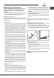
• If the cooker is installed
underneath a wall cabinet, there
must be a minimum distance of 420
mm between this cabinet and the
top of the hob.
This distance should be increased
to 700 mm if the wall cabinets are
ammable (see gure).
• Do not position blinds behind the cooker or less than 200
mm away from its sides.
• Any hoods must be installed in accordance with the
instructions listed in the relevant operating manual.
Levelling
If it is necessary to level the
appliance, screw the adjustable
feet into the places provided on
each corner of the base of the
cooker (see gure).
Electrical connection
THE EQUIPMENT MUST BE EARTHED CORRECTLY.
The appliance is designed for operation with an alternating
current at the power supply voltage and frequency indicated
on the data plate (this is located underneath the appliance;
alternatively the information may be found at the end of the
instruction manual).
Make sure that the local power supply voltage value is the
same as the value indicated on the data plate. The appliance
does not come with a power supply cable, because the size
of this cable should be determined according to the type of
electrical connection used (see connection diagram below).
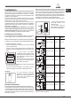
Use a H05RR-F-type rubber cable. Open the terminal board,
following the instructions for the adjacent gure:
To install the power supply cable, follow the instructions below:
2
1
1
2
3
4
5
V
• Loosen the cable clamp
screw “V” and the wire
contact screws.
• Fix the wires under the
screw heads in accordance
with the following diagram.
Electrical connection Power supply
voltage
Fuse
Cross-
section
230V -1+N ~ 50Hz 32* A 3x4 mm²
400V 2+N ~ 50Hz 32 A 4x4 mm²
400V -3+N ~ 50Hz 25 A 5x2.5 mm²
230V -2 ~ 50Hz 32* A 3x4 mm²
230V -3 ~ 50Hz 25 A 4x4 mm²
400V -2+2N ~ 50Hz 25* A 5x2.5 mm²
*Application of the simultaneity coefcient in compliance
with the relevant standard.