
User's Manual


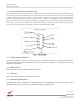


Table Of Contents
- Preface
- 1 Product Overview
- 2 Optimizing the System during Installation
- 3 Web-Based GUI
- 3.1 Web-Based GUI Session
- 3.2 System Status
- 3.3 Local Network
- 3.4 RF Configuration
- 3.5 Program a Filter
- 3.6 Remote Network
- 3.7 SNMP Configuration
- 3.8 Time Configuration
- 3.9 System Health
- 3.10 Install and Upload
- 3.11 Reboot
- 3.12 Alarm Configuration
- 3.13 Email Configuration
- 3.14 Log Configuration
- 3.15 Account Credentials
- 4 Console Interface
- 4.1 Text Menu Interface (Local Access)
- 4.2 Telnet Session (Remote Access)
- 4.3 Modem Interface (Remote Access with Login)
- 4.4 Additional Tips
- Appendix A Attenuation and Dynamic Range Guidelines
- Appendix B Band Plans and Filter File Naming Conventions
- Appendix C Mechanical Configurations
- Appendix D Mechanical and Electrical Specifications
- Appendix E Port Configurations
- Appendix F Acronyms and Abbreviations

Digital Repeater Line
DSP95 Series User’s Guide
Page 15 of 74
WESTELL.COM
1.877.844.4274 © 2016 Westell Technologies
25 May 2016 Doc. No. 960-1250-MNL rG
1 Product Overview
1.1 Product Information
Westell Technologies digital repeaters were developed for use within enclosed structures where sufficient signal
strength from local cell sites to operate cell phones is unavailable. Adequate signal strength must be available outside
the structure as a prerequisite to achieving in-building coverage. The digital repeater is connected to an external
antenna, usually on the roof, and to one or more internal antennas placed strategically throughout the area where
wireless service is desired.
The external antenna is typically a directional type, such as a Yagi antenna. Internal antennas are typically
omnidirectional, though
various other types may be used, depending on the coverage application. The Westell DSP
repeater amplifies both the uplink
(phone to tower) and downlink (tower to phone) signals, facilitating
communications to and from the intended wireless infrastructure.
With a maximum total of 90 dB nominal gain on both the uplink and downlink, gain can be adjusted over a range
from 58.5 dB to 90 dB in 0.5 dB steps. Control of the repeater is achieved utilizing a computer connected to a COM
port or via a crossover Ethernet cable connected to the Ethernet port.
A specific filtering process modifies each amplification chain. This process digitally converts the assigned spectrum
and then applies digital signal processing (DSP) techniques. DSP is used to create passbands that selects the RF
energy passing through either the uplink or downlink paths. After the digital processing is complete, the information
is converted back to an analog signal that is applied to the remaining stages of amplification. The resulting signals
emitted by the repeater are specific to the network service providers’ requirements. If these requirements change,
only the DSP configuration parameters must change. Configuration parameters are created at the factory and
supplied as files to be downloaded to the repeater. The filter set configurations stored in memory determine the
unit’s adaptability to various field applications. Appendix B describes the band plans and the convention Westell uses
to identify and store the files that make up the filter set. All Westell repeaters are shipped with an active filter set that
is programmed according to customer specifications. In most cases, the installer will not be required to program a
filter.
1.2 Functional Overview
Westell Technologies digital repeaters incorporate the following features for convenient operation, access, protection,
and control:
• Network configuration and control using either a web GUI accessed using a web browser or a menu
driven user interface using the serial port. The GUI does not require Internet access.
• User gain control (affects all passbands)
• Automatic gain control
• Automatic power control
• Overdrive protection (PA limiting)
• Under/Over voltage protection
• Fault protection
• Alarm notification - local/remote