
User Manual


Installation and Operator Handbook DRB-25 Diagnostics Monitor
AMX-MA-00656 Issue 0.02 (USA) 4
The Controller Module default communications settings are 9600 baud, 8 data bits, 1 stop bit and no parity
(8N1).
6.2.6 Getting Help
To get help on the Transceiver Module programmer, from the main menu activate the Help pull-down menu
and select Contents, Search or Index as required.
6.3 RUNNING THE DRB-25 DIAGNOSTIC MONITOR
Once DRB-25 Diagnostic Monitor is installed it will attempt establish communications with the Controller
Module and if successful the status dialog boxes will open automatically. The Main Screen provides access to
the following dialog boxes.
• File menu: The only option available is Exit.
• Configure: Dialog boxes for Configure Communications and Polling Interval.
• Status/Test: Status dialog boxes for Radio 1 Status, Radio 2 Status and Alarms; Test dialog boxes
for Radio 1 Test, Radio 2 Test and Change Test Password
• Help dialog box.
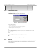
6.3.1 Configuration
From the main screen the Configure Menu gives access to configuring communication parameters and the
polling interval.
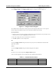
6.3.2 Configure Communications
The user will be prompted for Configure Communications dialog box if the DRB-25 Diagnostic Monitor is
unable to establish communications with the Controller Module or whenever Configure | Comms is selected
The following communications parameters may be set:
• Flow control (Xon or Xoff).
• Communications Port.
• Data Bits.
• Baud rate.
• Stop Bits.
• Parity.