ch t ch Vl taa am nz ko uig p sc ha Lu O nt s Ve tor rb ing ra sd nd ru in kk gs n m op an , s O lie ag ig po er na O m al nt p la m st m p M ek et ag in m ne gs ag et toe ne ve s nt tel etve ie nt l ie l Ve rg In ren st de e Ve lsc ling rs hro sb Vl tuiv ef v out am er o en o l Br voe ijn r d e an le st r uw Af der slu m sc o hi itd to jf r ek se l Ve rg H ren an d d e Br ve ling an rst sb In der ellin out st fle g e n el sc ns luc ht hr kle oe p fv oo rd e lu ch tk le p Info voor de vakman Montage- e
Conformiteitsverklaring volgens ISO/IEC Guide 22 Aanbieder : Max Weishaupt GmbH Adres : Max Weishaupt Straße D-88475 Schwendi Product : Type : Oliebrander met ventilator WL20/1-C WL20/2-C Inhoud 1 Fundamentele richtlijnen 3 2 Veiligheidsaanwijzingen 4 beschrijving 3 Technische 3.1 Doelgericht gebruik 3.2 Functie 5 5 6 De hierboven beschreven producten zijn conform met Document-nr.
1 Fundamentele richtlijnen Deze montage- en bedieningsrichtlijnen • zijn een vast bestanddeel van het toestel en moeten altijd bij de installatie bewaard worden. • zijn uitsluitend bestemd voor gekwalificeerde vakmensen. • omvatten de belangrijkste aanwijzingen voor een veilige montage, inbedrijfname en onderhoud van het toestel. • dienen in acht genomen te worden door alle personen die aan het toestel werken.
2 Veiligheidsaanwijzingen Gevaar bij de omgang met het toestel Weishaupt-producten zijn gebouwd overeenkomstig de geldende normen en richtlijnen en de algemeen erkende veiligheidstechnische regels.Toch kan bij ondeskundig gebruik levensgevaar optreden voor de gebruiker of voor derden en kan schade aan het toestel of aan andere goederen ontstaan.
3 Technische beschrijving 3 3.1 Doelgericht gebruik De Weishaupt oliebrander WL20 is geschikt : • voor montage op een warmtegenerator volgens EN 303-2 resp. DIN 4702-1 • voor warmwaterinstallaties bij intermitterende werking en continu bedrijf (verbrandingsmanager schakelt om de 24 h éénmaal af) • voor montage op een warmeluchtgenerator Voor andere toepassingen, afwijkend van deze voorschriften, is een schriftelijke toestemming van de firma Max Weishaupt GmbH noodzakelijk.
3 3.2 Functie Branderconstructie • Volautomatische oliedrukverstuivingsbrander met ventilator. • Eéntrapse bedrijfswijze.
3 Oliepomp AL30C 9537 • Pomp voor gasolieverwarming • Ingebouwd drukregelventiel • Eén magneetventiel ➀; stroomloos gesloten • Bypass voor de omschakeling van tweepijps- naar éénpijpssysteem Technische gegevens : Drukbereik van de pomp ___________________8…15 bar Aanzuigdebiet _______________________________40 l/h Fabrieksinstelling ____________________________12 bar Ontluchting De pompen ontluchten bij een tweepijpssysteem automatisch.
4 Montage 4.1 Veiligheidsaanwijzingen voor de montage Spanning van de installatie uitschakelen Voor het begin van de montagewerken de hoofd- en gevaarschakelaar uitschakelen. GEVAAR Negeren kan elektrische schokken veroorzaken, met zware verwondingen of de dood tot gevolg. 4.2 Levering, transport, opslag De levering controleren Controleer de levering op volledigheid en transportschade. Indien de levering onvolledig of beschadigd is, gelieve dit aan de leverancier te melden.
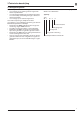
4 ➁ max. 20 m max. 4,6 m ➁ ➀ +H max. 3,5 m max. 3,5 m -weishaupt- raadt aan een magneetventiel (2) in de toevoerleiding in te bouwen. Het magneetventiel moet vertraagd sluiten en een drukontlasting in de richting van de olietank aanwijzen. Aansturing van het magneetventiel : zie hfst. 5.5. Principeschema olietoevoerleiding (niet volledig) max. 20 m max. 4,6 m Bij een hogerliggende oliespiegel t.o.v.
4 4.5 Brandermontage Warmtegenerator voorbereiden De afbeelding geeft een voorbeeld van een bemetseling voor een warmtegenerator zonder gekoelde voorwand. De bemetseling mag niet verder reiken dan de voorkant van de vlamkop. De bemetseling mag echter conisch (≥ 60°C) uitgevoerd worden. Bij warmtegeneratoren met watergekoelde voorwand is, voor zover de ketelfabrikant geen andere voorschriften hanteert, de bemetseling niet nodig.
4 4.6 Elektrische aansluiting ☞ Polariteit van de aansluitstekker controleren. Schakelschema zie hoofdstuk 5.5. Elektrische aansluiting ☞ Aansluiting op de voedingsspanning uitvoeren volgens het voor het toestel geldende aansluitschema. Aanwijzing voor Oostenrijk Voor de brander moeten scheidingselementen ingezet worden. Minstens 3 mm contactafstand; meerpolig werkend.
5 Inbedrijfname en werking 5.1 Veiligheidsaanwijzingen voor de eerste inbedrijfname De eerste inbedrijfstelling van de verbrandingsinstallatie mag alleen door de leverancier, fabrikant of een andere, door deze laatste erkende vakkundige uitgevoerd worden. Daarbij moet de juiste instelling en werking van alle regel-, sturings- en veiligheidscomponenten gecontroleerd worden.
5 5.3 Eerste inbedrijfname en afregeling Basisinstelwaarden stuwschijf en luchtklep Met de schaalwaarden voor de instelling van de stuwschijf en de luchtklep kan de brander voor de eerste inbedrijfname vooringesteld worden. De instelwaarden zijn gebaseerd op de maximale vuurhaardweerstand volgens EN 303 en moeten voor de optimalisatie van de verbranding aan de effectieve vuurhaardweerstand aangepast worden. Algemeen kunnen met deze voorinstelling CO2-waarden tussen 12,0 % en 13,0 % verkregen worden.
5 Richtwaarden druk vóór de menginrichting 5,5 -C /2 5,0 Druk [mbar] Richtwaarden voor de ventilatordruk vóór de menginrichting Werd de brander voor de eerste inbedrijfname ingesteld overeenkomstig de parameters in de diagrammen, dan bekomt men, afhankelijk van de vuurhaardweerstand van de warmtegenerator, de in het diagram aangegeven richtwaarden voor de druk voor de menginrichting.
5 5.
T1 T2 H1 S3 Aarding of nulgeleider volgens plaatselijke voorschriften 230V 1,N,PE 50/60Hz Max. 16A F1 S1 P ϑ ϑ P F3 L PE N N F2 X6 L K3 h H2 P1 B4 X3:12 B1 C1 F1 F7 F2 F3 H1 H2 M1 P1 P11 Verbrandingsmanager W-FM05 met stekkeraansluiting Vlamvoeler Motorcondensator Externe zekering (max. 16A traag) Externe zekering (max.
5 5.6 Bediening W-FM 05 Functie De in de W-FM 05 geïntegreerde ontgrendelingstoets met signaallamp vervult volgende functies: • ontgrendeling bij branderstoring • overdracht van een optische diagnosecode (zie hfst. 6). • optische data-overdracht (miet gebruikt) Afhankelijk van de uitgangssituatie (branderbedrijf of branderstoring) moet de lamp-drukknop 1 seconde of 5 seconden lang ingedrukt worden om de gewenste functie te starten.
6 Oorzaken en oplossen van storingen De brander wordt buiten bedrijf in storingsstand vergrendeld teruggevonden (signaallamp rood) of de branderwerking wordt verhinderd (signaallamp flikkert oranje/rood of groen/rood). OPGELET Bij storingen moeten eerst de basisvoorwaarden voor een normale werking gecontroleerd worden : ❏ Is er spanning aanwezig ? ❏ Is er stookolie in de tank ? ❏ Zijn alle regelorganen voor ruimte- en keteltemperatuur, laagwaterbeveiliging, eindschakelaars e.d.
6 Probleem Ooorzaak Oplossing brander werkt met zwakke belichting branderinstelling controleren ofwel is de vlamvoeler vuil Grenswaarden : kortsluiting in voelerkring : aanspreekgrens voor vreemdlicht: aanspreekgrens voor bedrijf: aanbevolen vlamcontrolestroom : max. bereikbare voelerstroom : <2 kΩ komt overeen >110µA <15µA >30µA 40 tot 100µA ca.
6 Probleem Ooorzaak Oplossing Verstuiver Ongelijkmatige verstuiving boorgat gedeeltelijk verstopt verstuiver vervangen verstuiverfilter sterk vervuild verstuiver vervangen door te lang gebruik versleten verstuiver vervangen Geen oliedoorgang verstuiver verstopt verstuiver vervangen Olie stroomt onmiddellijk bij de start van de brandermotor magneetventiel oliepomp ondicht oliepomp vervangen Vlamvoeler reageert niet op de vlam vlamvoeler defect vlamvoeler vervangen Vlamkop sterke cokesaansl
7 Onderhoud 7 7.1 Veiligheidsaanwijzingen voor onderhoud GEVAAR GEVAAR Onvakkundig uitgevoerde onderhouds- en herstellingswerkzaamheden kunnen zware ongevallen tot gevolg hebben. Personen kunnen daarbij zwaar gewond of gedood worden. Onderstaande veiligheidsrichtlijnen dienen absoluut in acht te worden genomen. Verbrandingsgevaar Bepaalde bouwdelen van de brander (b.v. vlamkop, branderflens, enz.) warmen op tijdens de werking. Laten afkoelen vooraleer servicewerken uit te voeren.
7 7.3 Verstuiver uit- en inbouwen Uitbouw Vervanging van de verstuiver WL20/1-C 1. Brander demonteren en in servicepositie ophangen (zie hfst. 4.5) 2. Ontstekingskabel uittrekken 3. Schroef losdraaien 4. Stuwschijf van de verstuiverlijn losmaken 5. Verstuiver uitnemen Bij het wegnemen van de verstuiver de verstuiverlijn tegenhouden. Brander Sleutelwijdte verstuiver / verstuiverlijn WL20/1-C: SW16 / SW 19 WL20/2-C: SW16 / SW 27 Inbouw De inbouw gebeurt in omgekeerde volgorde.
7 7.5 Menginrichting instellen Als vlamkop en stuwschijf sterke cokesaanzetting vertonen of sterk met olie vervuild zijn, dan moet de instelling van de menginrichting gecontroleerd worden. De maat S1 (afstand stuwschijf tot voorkant vlamkop) kan alleen gecontroleerd worden, wanneer de brander aan een uitzwenkbare keteldeur gemonteerd is. Indien dit niet mogelijk is zal de verstuiverlijn gedemonteerd worden (zie hoofdstuk 7.6) en moet de maat L gecontroleerd worden.
7 7.6 Verstuiverlijn uit- en inbouwen 7.
7 7.8 Servicepositie 7.9 Oliepomp, ventilatormotor en schoepenwiel uit- en inbouwen 3 5 Schroef toegankelijk via de boring in het schoepenwiel Bij de montage moet de schroef op de uitsparing van de motoras zitten.
7 7.10 Luchtregelhuis en luchtklep reinigen 2 7.
7 7.12 Oliepompfilter uit- en inbouwen T6,3H250V 7.
8 Technische gegevens 8.1 Branderuitrusting Brandertype Brandermanager Motor (optie) Servomotor WL20/1-C WL20/2-C W-FM05 ECK 04/F-2 W-St 02/1 230V, 50Hz 2750 min-1 0,25 kW, 1,5 A cond. 8 µF Schoepenwiel Ontstekingstoestel Vlamvoeler Oliepomp 160x60 W-ZG01 QRB1B AL30 C 9537 8.2 Werkingsveld WL20/1-C WL20/2-C Vlamkop Brandervermogen W20/1-C 50…120 kW 4,2…10,1 kg/h W20/2-C 70…150 kW 5,9…12,6 kg/h 3.0 3.0 2.5 2.5 Vuurhaarddruk [mbar] Vuurhaarddruk [mbar] Brandertype 2.0 1.5 1.0 0.
8 8.6 Afmetingen Maten in mm l1 l2 l3 l4 WL20/1-C 144 393 31 525 434 73 358 179 376 285 182 183 108 M8 170 130 123 150 WL20/2-C 174 393 31 558 434 73 358 179 376 285 182 183 120 M8 170 130 123 150 l5 l6 b1 b2 h1 h2 h3 h4 d1 d2 d3 d4 d5 d6 d3 d4 –weishaupt– d1 h3 h1 h2 d2 Aansluitmaten volgens EN 226 b1 l1 l2 l4 l5 d3 d5 d6 h4 b2 t = 15 mm l3 l6 Brandertussenflens voor vermogen < 70 kW (toebehoren) 8.7 Gewicht WL20/1-C Brander ________________________________ca.
A Bijvoegsel Inhoud • Verbrandingscontrole • Trefwoordenregister Verbrandingscontrole Opdat de installatie milieuvriendelijk, zuinig en storingvrij zou kunnen werken, zijn bij de afregeling rookgasmetingen noodzakelijk. Voorbeeld van een vereenvoudigde berekening voor de in te stellen CO2-waarde Gegeven: CO2 max. = 15,4 % Bepaling van rookgasverliezen Het zuurstofgehalte van de rookgassen, alsook het verschil tussen rookgas- en verbrandingsluchttemperatuur is te bepalen.
Trefwoorden A Afsluitventiel Antihevelventiel Aanzuigleiding B Basisinstelling menginrichting Basisinstelwaarden luchtklep/stuwschijf Bemetseling Buisleidinglengte Bypass A Blz.
Weishaupt-producten en service Olie-, gas- en combibranders van de typenserie W en WG/WGL – tot 570 kW Zij worden bij voorkeur ingezet in één- en meergezinswoningen. Voordelen: volautomatische betrouwbare werking, goede toegang tot de afzonderlijke bouwdelen, makkelijke service, geluidsarm, energiebesparend. Olie-, gas- en combibranders van de typenserie Monarch, R, G, GL, RGL – tot 10.900 kW Zij worden ingezet voor alle soorten en groottes van centrale verwarmingsinstallaties.