
Installation Guide


15
Before installing, draw an installation plan showing
the placement of the fixings guides, heating cables,
floor sensor, and junction box or boxes.
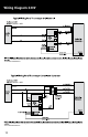
It is important to mark the location of the cold lead
joint on the plans. The cold lead is the non-heating
portion of the cable that will run in the wall to
connect the system to the thermostat. The heating
cable shall not extend beyond the room or area in
which it originates.
Marking the heating cable layout on floor plan
makes it easier to trace back the heating cable for
trouble shooting purpose. Keep such a layout filed after installation.
Before installing the heating cables, refer to the spacing guide below to ensure you have the
correct number and size of heaters for the area you wish to heat.
Installing the Fixing Guides
When using 12” Warmup Fixing Strips to secure the
cable to the subfloor, use the following provisions to
ensure proper spacing of the cable. The fixing guides
included in the kit are 12” (300mm) long with 1” spac-
ing guides.
The perimeter fixing guides should be installed a min-
imum of 3 inches away from the wall in the oppo-
site direction to the cable runs (Additional stabilizing
guides could be laid 40 inches apart across the floor).
The Warmup Fixing Strips can be secured to the floor
using hot glue, nails, screws or strong double-sided
tape
It may be necessary to cut the guides into smaller sec-
tions to accommodate irregular shaped rooms. The
strips can be secured to the floor using hot glue, nails
or screws.
Once you have fitted the cable strips, the heating cable
may be laid out.
Spacing Guide
For precise calculation of spacing between loops (OCS), we recommend you use the following
calculation using the cable lengths given on page 4. For additional clarification please call our
technical support line: US: 1-888-927-6333 or Canada: 1-888-592-7687
OCS (On Center Spacing)=Area (sq ft) × 12
Length (ft)
Planning Your Installation