
Specifications


QUADRAPADDLE SIGNAL CONTACTS AND MODULES USER’S MANUAL: SECTION 1 VIRGINIA PANEL CORPORATION
1/26/10
1-1 For more information visit vpc.com
TOOLS REQUIRED
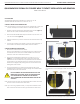
Crimp Tool, Part # 910 101 125
CRIMP TOOL SETUP
1. Using the Crimp Tool, Part # 910 101 125 (Figure A), with the wire
gauge numbers facing you, squeeze the tool handles together
until the ratchet releases; this will open the tool.
2. Place the contact into the crimp die cavity from the rear side of
the tool. The contact crimp areas will be facing you. Move the
contact up to align the contact on the insulation stop (Figure B).
Place contact into the correct wire cavity (24-28 AWG on the left,
22-24 AWG on the right) according to the wire gauge size in Table
1. Squeeze the crimp handles until ratchet clicks one time to hold
contact in place.
CONTACT SETUP AND CRIMPING
1. Determine the strip length according to wire gauge (Table 1).
Strip wire (Figure C).
2. Insert the wire through the insulation stop and into the wire barrel
of the contact until it stops against the insulation stop.
3. Holding the wire in place, squeeze the handles together until the
tool is completely closed. Continue squeezing, until the last click,
to allow the handle to release fully. Remove the contact from
the cavity (Figure D). The conductor shall be visible on both ends
of the conductor crimp. The insulation crimp should grip securely
around the wire insulation without deforming the insulation.
4. Check to make sure the wire meets the minimum pullout force
shown in Table 1 and the wire and insulation barrel are within the
height and width specications. Measure the crimp height with
an anvil and point micrometer.
QUADRAPADDLE™ SIGNAL RECEIVER CONTACT ASSEMBLY
PART # 610 138 116
Table 1.
WIRE SIZE,
AWG
CRIMP
TOOL
LOCATOR
DIE
STRIP LENGTH
IN [MM]
INSULATION DIAMETER
MAX (IN [MM])
WIRE BARREL CRIMP
MAX (IN [MM])
PULLOUT FORCE
(LBS [N])
EXTRACTION
TOOL
22
910 101 125 N/A
0.125
[3.18]
0.048
[1.22]
0.034 - 0.038
[0.86 - 0.96]
10 [44.5]
910110112
24*
0.032 - 0.036
[0.81 - 0.91]
8 [35.6]
26
0.040
[1.02]
0.028 - 0.032
[0.71 - 0.81]
4 [17.8]
28
0.024 - 0.030
[0.61 - 0.76]
2 [8.9]
2-30* 1 [4.4]*
*Pullout force is for individual wires.
[3.18]
.125
Figure A. Crimp Tool, Part # 910 101 125.
Figure D. Correctly crimped contact.
Figure C. Correctly stripped wire.
Figure B. Insulation stop on crimp tool. Note: Larger
diameter 24 AWG wire, greater than 0.04” should be
crimped using the 22-24 crimp die.
Dimensions shown: [millimeters]
inches
24-28 AWG 22-24 AWG
INSULATION
CRIMP
CONDUCTOR CRIMP