Installation Guide LPKPDR - Universal LP Conversion Kit for Professional & Designer Ranges/Rangetops
Table of Contents Warnings __________________________________________________________________ 3 Kit Contents _______________________________________________________________ 4 Regulator Conversion ________________________________________________ 5 Infrared Broiler Conversion ____________________________________________ 6 Surface Burner Conversion Sealed Type 1_____________________________________________________ 7 Sealed Type 2 _____________________________________________________ 8 Designer Range & Rangetop
IMPORTANT–Please Read and Follow! DANGER Fire/explosion hazard. IF THE INFORMATION IN THIS MANUAL IS NOT FOLLOWED EXACTLY, A FIRE OR EXPLOSION MAY RESULT CAUSING PROPERTY DAMAGE, PERSONAL INJURY, OR DEATH. • DO NOT store or use gasoline or other flammable vapors and liquids in the vicinity of this or any other appliance. • WHAT TO DO IF YOU SMELL GAS: –DO NOT try to light any appliance. –DO NOT touch any electrical switch; DO NOT use any phone in your building.
LP Orifice Conversion Kit Contents Burner Type Size Quantity Infrared Broiler Sealed Type 1 56 1.1 (1) (8) Sealed Type 2 1.
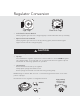
Regulator Conversion V E NT R RV48CL P 1/2 PSIG NAT-5 Flip Cap • LPG-10 Hex Nut Cap Sealed Surface Burner Models Identify regulator type from rear of range/rangetop located underneath main top assembly. • Open Surface Burner Models Identify regulator type from front of unit by removing grates, burner bowls and grate support from far left side of range/rangetop. CAUTION Before proceeding with conversion, turn off gas supply and disconnect power to unit.
Infrared Broiler Conversion IMPORTANT: The infrared broiler orifice must be changed from rear of range before unit is installed. Locate bag labeled IR Broiler Orifice. Remove nut securing 90 degree fitting and broiler tubing to rear of range. Broil Nut Remove Orifice from 90 degree fitting and replace with orifice from bag labeled IR Broiler Orifice. Reverse procedure as needed to reassemble.
Surface Burner Conversion Sealed Type 1 Item #1 Item #2 Locate bag labeled Sealed Burner Orifice Type 1. Remove the venturi (Item #1) by turning counterclockwise. Use a 11/32” (9 mm) socket or nut driver to remove orifice (Item #2) and replace it with orifice from bag labeled Sealed Burner Orifice Type 1. Tech Tip: Tape can be applied to the inside of a socket to assist in retrieval of the surface burner orifices. This can prevent the orifices from falling into the range during removal.
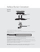
Surface Burner Conversion Sealed Type 2 Item #1 Item #2 Item #3 Locate bag labeled Sealed Burner Orifice Type 2. NOTE: If the burner is a PowerPlus™ Burner (check control panel), use orifice kit 011915-000 to convert this burner only. WARNING DO NOT use this orifice for any other top burners. Remove the screws (Item #1) and set burner base aside (Item #2). IMPORTANT: Burner bases must be handled carefully to prevent igniter wires from becoming disconnected.
Surface Burner Conversion Designer Range & Rangetop Item #1 Item #2 Item #3 Locate bag labeled Designer Burner Orifice. Remove the screws (Item #1) and set burner base aside (Item #2). IMPORTANT: Burner bases must be handled carefully to prevent igniter wires from becoming disconnected. Loose igniter wires may fall through top assembly. Use a 5/16” socket or nut driver to remove orifice (Item #3) and replace it with orifice from bag labeled Designer Burner Orifice.
Orifice Locations (#61) (#65) (#57) (#67) DGRT301 (#63) (#65) (#57) (#61) (#67) DGRT361 (#60) (#67) (#58) (#70) DCCG130 DSCD130 10
Surface Burner Conversion Open Burner Type 3 Adjustment Screw Air Shutter Locate bag labeled Open Burner Orifice Type 3. Remove screws securing open surface burner to burner box and remove open surface burner. NOTE: Igniter wire must be disconnected to remove burner. Loosen air shutter screw and adjust opening to 7/16” and tighten air shutter screw. Locate orifice mounted onto gas valve behind control panel. NOTE: This can be accessed through the burner box area. Control panel does not require removal.
Griddle Conversion (for models equipped with griddle) U-Shape Burner with Spark Ignition Air Shutter Air Shutter Set Screw Vol Adjustment Screw Air Shutter Orifice Hood Locate bag labeled Griddle Orifice. Remove screws securing griddle venturi plate to griddle box and remove griddle venturi plate. Remove screws securing griddle burner to burner box. Loosen air shutter screw and adjust opening on burner to 7/16” and tighten air shutter screw.
Griddle Conversion (for models equipped with griddle) Straight Tube Burner with Spark Ignition Screw (Front of Burner) Screw (Rear of Burner) Adjustment Screw Air Shutter Locate bag labeled Griddle Orifice. Remove screws securing griddle venturi plate to griddle box and remove griddle venturi plate. Remove screws securing griddle burner to burner box. Loosen air shutter screw and adjust opening on burner to 7/16” and tighten air shutter screw.
Griddle Conversion (for models equipped with griddle) Straight Tube Burner with Glow Bar Ignition Screw (Front of Burner) Screw (Rear of Burner) Adjustment Screw Air Shutter Remove screws securing glow bar igniter to burner box and place glow bar igniter aside. Remove screws securing metal plate to burner box located underneath griddle burner and remove metal plate. Remove screws securing griddle burner to unit and remove griddle burner.
Grill Conversion (for models equipped with grill) Lift flavor grids from unit. Lift flavor grid support from unit. Remove screws securing rear bracket to burner box. Remove screws securing flame shield to burner box. Lift out left and right side burner box liners. Remove screws securing burner to burner box. Loosen air shutter screw and adjust opening on burner to 7/16” and tighten air shutter screw. Remove orifice by turning counterclockwise and replace with orifice from bag labeled Grill Orifice.
Wok Conversion (for models equipped with wok) Overhead View Air Shutter Orifice Remove center trivet and/or grates, center ring and grate support. Lift and remove burner from unit. Loosen air shutter screw and adjust opening on burner to 5/8” and tighten air shutter screw. Remove orifice by turning counterclockwise and replace with orifice from bag labeled Wok Orifice. IMPORTANT: The orifice tip must be located 3/16” inside the burner for proper gas mixture and combustion.
Bake Conversion “L” Shaped Air Shutter Adjustment Screw Remove oven racks and rack supports. Remove oven bottom by sliding toward rear of range, then lift upward. Remove screws securing toe grille to unit. Remove screws securing burner support bracket to frame of unit and remove burner support bracket. Slide bake burner to the left off of orifice and pull bake burner straight out through available clearance. Loosen air shutter screw and adjust opening on burner to 7/16” and tighten air shutter screw.
Bake Conversion “U” Shaped Air Shutter Air Shutter Set VolScrew Adjustment Screw Air Shutter Orifice Hood Remove oven racks and rack supports. Remove oven bottom. Remove screws securing bake igniter to bake burner. Remove screws securing bake burner shield to oven burner box. Remove screws securing bake burner to oven burner box. Loosen air shutter screw and adjust opening on burner to 3/8” and tighten air shutter screw.
Rating Label Locations When LP/Propane conversion is complete, complete the enclosed conversion label and place it next to the rating label. The rating label locations can be found as follows: Professional Open Burner Range & Rangetop - On the interior left side of the burner box. To access this label, remove the left side grates and grate support. Professional Sealed Burner Range & Rangetop - Under the control panel. Designer Sealed Burner Range & Rangetop - Under the control panel.
Viking Range, LLC 111 Front Street Greenwood, Mississippi 38930 USA (662) 455-1200 For product information, call 1-888-845-4641 F20525F EN (061518)