
User's Manual


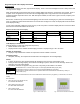

Table Of Contents
- Viconics
- Part
- Numbers
- 1. (None): No function will be associated with the input
- 4. (Filter): a backlit flashing Filter alarm will be displayed on the thermostat LCD screen when the input is energized. It can be tied to a differential pressure switch that monitor filters
- 5. (Service): a backlit flashing Service alarm will be displayed on the thermostat LCD screen when the input is energized. It can be tied in to the AC unit control card, which provides an alarm in case of malfunction.
- 1. (None): No function will be associated with the input
- 2. (COC/NH) Change over dry contact. Normally Heat: Used for hot / cold water change over switching in 2 pipe systems.
- Contact closed = Cold water present
- Only used and valid if system is setup as 2 pipes. Parameter ( Pipe No ) set as 2 pipes.
- 3. (COC/NC) Change over dry contact. Normally Cool: Used for hot / cold water or air change over switching in 2 pipe systems.
- Contact closed = Hot water present
- Only used and valid if system is setup as 2 pipes. Parameter ( Pipe No ) set as 2 pipes.
- 4. (COS) Change over analog sensor: Used for hot / cold water or air change over switching in 2 pipe systems.
- Only used and valid if system is setup as 2 pipes. Parameter ( Pipe No ) set as 2 pipes.
- 5. (SS) Supply air sensor monitoring: Used for supply air temperature monitoring.
- Only used for network reporting of the supply air temperature. Has no internal function in the thermostat.
- Range is: 0 to 500
- This parameter (Personal Area Network Identification) is used to link specific thermostats to a single specific Viconics wireless gateway ( VWG ) For every thermostat reporting to a gateway ( maximum of 30 thermostats per gateway ), be sure you set the SAME PAN ID value both at the gateway and the thermostat(s).
- Range is: 10 to 26
- Viconics recommends using only the 2 last channels ( 25-2575MHz and 26-2580MHz )
- Range is: 0 to 254
- This parameter / function is not currently supported by the wireless thermostats.
- BI1
- Default value = None
- (None): No function will be associated with the input
- (Filter): a backlit flashing Filter alarm will be displayed on the thermostat LCD screen when the input is energized. It can be tied to a differential pressure switch that monitor filters
- (Service): a backlit flashing Service alarm will be displayed on the thermostat LCD screen when the input is energized. It can be tied in to the AC unit control card, which provides an alarm in case of malfunction.
- UI3
- Default value = None
- (None): No function will be associated with the input
- (COC/NH) Change over dry contact. Normally Heat: Used for hot / cold water or air change over switching in 2 pipe systems.
- Contact closed = Cold water or air present
- Only used and valid if system is setup as 2 pipes. Parameter ( Pipe No ) set as 2 pipes.
- (COC/NC) Change over dry contact. Normally Cool: Used for hot / cold water or air change over switching in 2 pipe systems.
- Contact closed = Hot water present
- Only used and valid if system is setup as 2 pipes. Parameter (Pipe No ) set as 2 pipes.
- (COS) Change over analog sensor: Used for hot / cold water or air change over switching in 2 pipe systems.
- Only used and valid if system is setup as 2 pipes. Parameter (Pipe No ) set as 2 pipes.
- (SS) Supply air sensor monitoring: Used for supply air temperature monitoring.
- 2.0 Pipes, will limit the number of sequences of operation available from 0 to 3

8
Remote sensor accessories
Model no. Description
S3010W1000 Wall mounted temperature sensor
S3020W1000
Wall mounted temperature sensor with override button and
occupancy status LED
S2060A1000 Averaging temperature sensor
S2000D1000 Duct mounted temperature sensor
Remote mount temperature sensors use 10K type 2 NTC thermistors.
Features:
• Each sensor can be configured for various averaging combinations
FIG.8 – S3020W1000 WALL
MOUNTED SENSOR
• Optional occupancy led
• Optional override key
Wiring example of single remote room sensor:
Wiring examples of 2 remote room sensors for averaging applications:
S3020W1000
Remote wiring 1 sensor
S2=On, S3=On
VT7300 Series
Thermostat
BO 5
BI 2
RS
Scom
Scom
RS
Scom
RS
C
DI
Aux
Scom
RS
Scom
RS
OR
S3010W1000
Remote wiring 1 sensor
S2=On, S3=On
24 Vac
Com
1
2
ON
Dip switch
setting for:
1 senso
r
S2-1 = ON
S2-2 = ON
VT7300 Series
Thermostat
1 x S3010W1000 and 1 x S3020W1000
Remote wiring 2 sensors
S1=On, S2=Off
Scom
RS
Scom
RS
2 x S3020W1000
Remote wiring 2 sensors
S2=On, S3=Off
Scom
RS
Scom
RS
C
DI
Aux
VT7300 Series
Thermostat
BO 5
BI 2
RS
Scom
24 Vac
Com
Scom
RS
Scom
RS
C
DI
Aux
Scom
Scom
RS
Scom
RS
RS
Wiring examples of 3 remote room sensors for averaging applications:
Temperature vs resistance chart for 10 Kohm NTC thermistor (R
25°C
= 10KΩ±3%, B
25/85°C
= 3975K±1.5%)
ºC ºF Kohm
ºC ºF Kohm ºC ºF Kohm ºC ºF Kohm ºC ºF Kohm
-40 -40 324.3197 -20 -4 94.5149 0 32 32.1910 20 68 12.4601 40 104 5.3467
-35 -31 234.4009 -15 5 71.2430 5 41 25.1119 25 77 10.0000 45 113 4.3881
-30 -22 171.3474 -10 14 54.1988 10 50 19.7390 30 86 8.0694 50 122 3.6202
-25 -13 126.6109 -5 23 41.5956 15 59 15.6286 35 95 6.5499 55 131 3.0016
Notes for averaging applications:
• S3010W1000 and S3020W1000 can be
mixed matched.
• S3010W1000 and S3020W1000 are to
be wired in parallel.
• Respect the dip switch setting in each
remote sensor.
1
2
ON
Dip switch
setting for:
2 sensors
S2-1 = OFF
S2-2 = ON
1
2
ON
Dip switch
setting for:
3 sensors
S2-1 = OFF
S
2
-
2
=
OFF
2x S3010W1000 and 1 x S3020W1000
Remote wiring 3 sensors
S2=Off, S3=Off
Scom
RS
Scom
RS
Scom
RS
Scom
RS
VT7300 Series
Thermostat
BO 5
BI 2
RS
Scom
24 Vac
Com
Scom
RS
Scom
RS
C
DI
Aux
3x S3010W1000
Remote wiring 3 sensors
S2=Off, S3=Off
Scom
RS
Scom
RS
Scom
RS
Scom
RS
VT7300 Series
Thermostat
RS
Scom
Scom
RS
Scom
RS
BO 5
BI 2
24 Vac
Com
Aux
C
DI
2 x S3010W1000
Remote wiring 2 sensors
S2=On, S3=Off
Scom
RS
Scom
RS
VT7300 Series
Thermostat
RS
Scom
Scom
RS
Scom
RS