Direct Vent Rear Vent Model BHDR36 Installation Instructions & Homeowner's Manual WARNING! IF THE INFORMATION IN THIS MANUAL IS NOT FOLLOWED EXACTLY, A FIRE OR EXPLOSION MAY RESULT CAUSING PROPERTY DAMAGE,PERSONAL INJURY OR LOSS OF LIFE. FOR YOUR SAFETY FOR YOUR SAFETY WHAT TO DO IF YOU SMELL GAS: DO NOT STORE OR USE GASOLINE OR OTHER FLAMMABLE VAPOURS AND LIQUIDS IN THE VICINITY OF THIS OR ANY OTHER APPLIANCE. * * • * * Do not try to light any appliance. Do not touch any electric switch.
TABLE OF CONTENTS PLEASE READ THE INSTALLATION & OPERATING INSTRUCTIONS BEFORE USING APPLIANCE. Thank you and congratulations on your purchase. IMPORTANT: Read all instructions and warnings carefully before starting installation. Failure to follow these instructions may result in a possible fire hazard and will void the warranty. Installation Instructions ...........................................................................................................................................
INSTALLATION INSTRUCTIONS IMPORTANT: PLEASE REVIEW THE FOLLOWING CAREFULLY This gas appliance should be installed by a qualified installer in accordance with local building codes and with current CAN / CGA-B149 (. 1 or .2) Installation codes for Gas Burning Appliances and Equipment. or for U.S.A Installations follow local codes and/ or the current National Fuel Gas Code. ANSI Z223.1. Remove any plastic from trim parts before turning the fireplace ON.
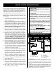
FIREPLACE DIMENSIONS M O N M ROD ROH ROW A FRAMING & FINISHING E B C B F J K L H I A D G BHDR36 A 36" 914mm B 34 1/4" 870mm C 21" 533mm D 33" 838mm E 24" 610mm F 16" 406mm G 19" 483mm H 23 7/8" 606mm I 27 1/2" 698mm J 6 3/4" 171mm K 10" 254mm L 13 1/2" 343mm M 41 5/8" 1057mm N 58 7/8" 1495mm O 29 7/8" 748mm ROD 16 1/2" 419mm ROW 36 1/2" 927mm ROH 35" 889mm -4- Fig.
CLEARANCE TO COMBUSTIBLES MANTELS Depending on the width of the mantel it may be installed higher or lower from the top of the louvre opening. See drawing and chart below for proper installation height of your combustible mantel piece. Non-combustible mantels may be installed at any height above the appliance opening. Back ........ 0 mm/0 inches Side ......... 0 mm/0 inches Floor ........ 0 mm/0 inches Top ..........
FINAL FINISHING CERTIFIED TO Non-combustible materials such as brick and tile can be extended over the outer face of the unit (Do not cover louvres or glass door). If a Trim Kit is going to be installed, brick and tile will have to be installed flush with the side of this appliance. ANSI Z21.88a-1998 / CSA 2.33a-M98 Vented Gas Fireplace Heaters Do not use this fireplace if any part of it has been under water.
GAS LINE INSTALLATION REMOTE SWITCH INSTALLATION FOR RN/RP 1. Thread wire through the electrical knockout located on either side of fireplace.. Do not cut wire or insulation on metal edges. Ensure that wire is protected. Run the other end to a conveniently located wall receptacle box. 2. Attach wire to switch and install switch into receptacle box. Attach cover plate to switch. 3. Connect wiring to gas valve. (Fig. 8/9) When purging gas line the front glass must be removed.
GENERAL VENTING INFORMATION Your fireplace is approved to be vented either through the side wall, or vertical through the roof. There must not be any obstruction such as bushes, garden sheds, fences, decks or utility buildings within 24" from the front of the termination hood. - Do not locate termination hood where excessive snow or ice build up may occur. Be sure to check vent termination area after snow falls, and clear to prevent accidental blockage of venting system.
Termination Clearances Termination clearances for buildings with combustible and noncombustible exteriors. Inside Corner A V Recessed Location Outside Corner A= Combustible 6"(152mm) Noncombustible 2"(50mm) D B= Combustible 6"(152mm) Noncombustible 2"(50mm) V C C E V B Balcony with perpendicular side wall Balcony with no side wall G C = Maximum depth of 48" (1219mm) for recessed location.
REAR VENTING APPLICATIONS STEP 1 Locate vent opening on wall. Note: It is not necessary to seal the vent pipe joints for any rear vent applications. Vent Opening — Combustible Wall Minimum clearances between vent pipe and combustible materials are as follows: Top Sides Bottom (240mm) 9-3/8" - 2" (50 mm) - 1" (25 mm) - 1" (25 mm) 10-3/8" (265mm) Note: Vent Starter Kit Model 7DVRVT must be used in rear vent applications. (framing detail) Maximum Vent Length .........................................
STEP 5 VERTICAL SIDEWALL INSTALLATIONS Guide the vent termination 4" collar into the 4" pipe then the 7" collar into the 7" pipe. Do not force the venting into position. If the pipes do not line up with the termination collars, disassemble elbows or pipes and reattach to the fireplace collar. (Fig.
The maximum numberINSERT of elbow degrees in a system is 270 o. (This does not include transition elbow from rear vent to vertical vent.) Fig. 20. VERTICAL SIDEWALL APPLICATIONS The maximum number of 90 degree elbows per side wall installation is four (4), (includes 7DVRT90 off back of unit) Sample: The maximum number of 45 degree elbows permitted per side wall installation is two (2). These elbows can be installed in either the vertical or horizontal run.
VENT SIDEWALL INSTALLATION HOW TO USE THE VENT GRAPH 1. Determine the height of the centre of the horizontal vent pipe exiting through the outer wall. Using this dimension on the Sidewall Vent Graph (Fig. 21), locate the point it intersects with the slanted graph line. 2. From the point of this intersection, draw a vertical line to the bottom of the graph. 3. Select the indicated dimension, and position the fireplace in accordance with same. (See examples Fig. 21).
STEP 2 STEP 5 Fig. 25. Measure wall thickness and cut adjustable zero clearance sleeve parts to proper length (MAXIMUM 12"). Adjust sleeve to minimum (9-3/8" x 9-3/8") and attach to firestop with #8 sheet metal screws (supplied). Install STEP 2assembly. firestop (Fig. 28) Use the appropriate length of pipe section – telescopic or fixed – and install. The 20" section of pipe which goes through the wall is packaged with the 7DVSK kit, and can be cut to suit if necessary. Fig.
DO NOT BACK FILL AROUND SNORKEL. SOIL SHOULD NOT BE LESS THAN 4" BELOW SNORKEL. BELOW GRADE INSTALLATIONS When it is not possible to meet the required vent terminal clearances of 12 inches (305mm) above grade level a model #7DVSKS vent kit is recommended. It allows installation depth of down to 7 inches (178mm) below grade level. The 7 inches is measured from the centre of the horizontal vent pipe as it penetrates through the wall.
c) A minimum of an 8 ft. vertical rise. d) Two sets of 45 degree elbow offsets within these vertical installations. From 0 to a maximum of 8 ft. a vent pipe can be used between elbows. (Fig. 33) e) 7DVCS must be used to support offsets. (Fig. 34) This application will require that you first determine the roof pitch and use the appropriate 7DVSKV (A,B or F). (see Venting Components, page 18) VERTICAL THRU THE ROOF INSTALLATION 1. Locate your fireplace. 2.
CRIMPED END VENTING COMPONENTS 7DVRVT - Through the wall Rear Vent Termination Starter Kit -Model 7DVSK - Sidewall Venting Starter Kit - Model 7DVSKV - Vertical Venting for 7DVSKV-A order 1/12 to 6/12 roof pitch for 7DVSKV-B order 7/12 to 12/12 roof pitch for 7DVSKV-F order flat roof Starter Kit - Model 7DVSKS -Snorkel Kit for Below Grade Installation 45o elbow kit 7DVR45 for Rear Vent Applications 7DVT45 for Vertical Installation Offsets 90o transition elbow kit 7DVRT90 for Vertical Sidewall Applications
GENERAL INFORMATION ON ASSEMBLING THE TWIST LOCK VENT PIPES When using CFM Majestic twist lock pipe it is not necessary to use silicone to seal the twist lock joints. The only areas that need silicone are the collars on the fireplace, the telescoping pipe (if used) and the horizontal termination connection (when necessary). REAR VENTING APPLICATIONS Note: It is not necessary to seal the vent pipe joints for any rear vent applications.
STEP 3 REAR WALL INSTALLATIONS Measure from fireplace collar or elbow face to face of outside wall (add 1-1/2" for vent pipe overlap). Mark pipes and cut to length. It is very important that the two pipes are flush with the outside wall once the fireplace is in its final location. Minimum clearance between vent pipes and combustible materials in one (1") inch (25 mm) on sides and bottom and two (2") inch (50 mm) on top. STEP 1 Locate vent opening on wall.
VERTICAL SIDEWALL APPLICATIONS VERTICAL SIDEWALL INSTALLATIONS Since it is very important that the venting system maintain its balance between the combustion air intake and the flue gas exhaust, certain limitations as to vent configurations apply and must be strictly adhered to. The maximum number of 90 degree elbows per side wall installation is four (4), (includes 7TDVRT90 off back of unit) The maximum number of 45 degree elbows permitted per side wall installation is two (2).
HOW TO USE THE VENT GRAPH 84" 2134mm 120" 3048mm 1. Determine the height of the centre of the horizontal vent pipe exiting through the outer wall. Using this dimension on the Sidewall Vent Graph (Fig. 47), locate the point it intersects with the slanted graph line. 2. From the point of this intersection, draw a vertical line to the bottom of the graph. 3. Select the indicated dimension, and position the fireplace in accordance with same. (See examples Fig. 45).
VENT SIDEWALL INSTALLATION STEP 2 Fig. 51. Measure wall thickness and cut adjustable zero clearance sleeve parts to proper length (MAXIMUM 12"). Adjust sleeve to minimum (9-3/8" x 9-3/8") and attach to firestop with #8 sheet metal screws (supplied). Install STEP 2assembly. firestop *IMPORTANT* Minimum clearance between vent pipes and combustible materials is one (1") inch (25 mm) on bottom, sides and top.
STEP 5 Fig. 54 (Fig. 54) Use the appropriate length of pipe section – telescopic or fixed – and install. The 20" section of pipe which goes through the wall is packaged with the 7TDVSK kit, and can be cut to suit if necessary. Sealing vent pipe and firestop gaps with high temperature sealant will restrict cold air being drawn in around fireplace.
DO NOT BACK FILL AROUND SNORKEL. SOIL SHOULD NOT BE LESS THAN 4" BELOW SNORKEL. FOUNDATION RECESS c) A minimum of an 8 ft. vertical rise. d) Two sets of 45 degree elbow offsets within these vertical installations. From 0 to a maximum of 8 ft. a vent pipe can be used between elbows. (Fig. 59) e) 7DVCS must be used to support offsets. (Fig. 60) This application will require that you first determine the roof pitch and use the appropriate 7TDVSKV (A,B or F).
VERTICAL THROUGH THE ROOF INSTALLATION 1. Locate your fireplace. 2. Plumb to centre of the (4") 90o transition elbow (7TDVRT90) from ceiling above and mark position. 3. Cut opening equal to 9-3/8" x 9-3/8" (240 mm x 240 mm). 4. Proceed to plumb for additional openings through the roof. In all cases, the opening must provide a minimum of 1 inch clearance to the vent pipe, i.e., the hole must be at least 9-3/8" x 9-3/8" (240 mm x 240 mm). 5. Place fireplace into position and secure to floor. 6.
TWIST LOCK VENTING COMPONENTS 7DVRVT - Through the wall Rear Vent Termination Starter Kit -Model 7TDVSK - Sidewall Venting Starter Kit - Model 7TDVSKV - Vertical Venting for 7TDVSKV-A order 1/12 to 6/12 roof pitch for 7TDVSKV-B order 7/12 to 12/12 roof pitch for 7TDVSKV-F order flat roof Starter Kit - Model 7TDVSKS -Snorkel Kit for Below Grade Installation 45o elbow kit 7TDV45 for Vertical/Horizontal Offsets 90o transition elbow kit 7TDVRT90 for Vertical Sidewall Applications or thru-the-roof.
OPERATING INSTRUCTIONS GENERAL GLASS INFORMATION GLASS FRAME FIREPLACE FRONT Only glass approved for use in Majestic products may be used for replacement. 1 . The use of subsitute glass will void all product warranties. 2. Care must be taken to avoid breakage of the glass. 3. Under no circumstances should this appliance be operated without the front glass or with a broken glass. Replacement of the glass (with gasket) as supplied by the manufacturer should be done by a licenced qualified service person.
INSTALLATION OF LOGS LAVA ROCK 1 . Remove front glass. (See "Glass Removal" Section) 2. Remove logs from the packaging. The lava rock provided with this fireplace must be placed on the firebox base on either side of the burner assembly. As with all plastics — these are not toys and should be kept away from children and infants. Under no circumstances should this lava rock be placed on any part of the burner assembly. 3.
MAINTENANCE FLAME CHARACTERISTICS It is important to periodically perform a visual check of the pilot and the burner flames. Compare them to the pictorials illustrated below (Fig. 70, 71 and 72). If any of the flames appear abnormal call a service person. 1. It is important to keep the burner and the burner compartment clean. This must be done periodically, at least once per season. 2. Clean the brass trim using a soft clean cloth, slightly dampened with lemon oil and buff with a soft clean cloth.
LIGHTING AND OPERATING INSTRUCTIONS FOR YOUR SAFETY READ BEFORE LIGHTING WARNING: If you do not follow these instructions exactly, a fire or explosion may result causing property damage, personal injury or loss of life. A. This fireplace has a pilot which must be lit manually. When lighting the pilot follow these instructions exactly. BEFORE LIGHTING smell all around the fireplace area for gas. Be sure to smell next to the floor because some gas is heavier than air and will settle on the floor. B.
TROUBLE SHOOTING THE GAS CONTROL SYSTEM HONEYWELL MILLIVOLT VALVE START CHECK • GAS SUPPLY ON NO YES PILOT LIGHTS WITH PIEZO IGNITOR NO YES PILOT STAYS LIT YES • LOCKOUT HAS ENGAGED. WAIT 60 SECONDS AND TRY AGAIN. • FOR SPARK AT ELECTRODE WHILE DEPRESSING PIEZO — 1/8" GAP TO PILOT HOOD NEEDED. • ALL WIRING CONNECTIONS • REPLACE PIEZO IGNITOR NO • FOR AIR IN THE LINES • THERMOPILE NEEDS A MINIMUM 325mV. ADJUST PILOT FLAME HEIGHT. • ALL WIRING CONNECTIONS.
TROUBLE SHOOTING THE GAS CONTROL SYSTEM SIT 820 NOVA MILLIVOLT VALVE GLASS DOOR TO BE REMOVED BEFORE SERVICE WORK CHECK NO GAS SUPPLY ON ▼ START • SHUTOFF VALVE OPEN • CONFIRM GAS HOOK-UP ▼ NO • • • • ▼ LIGHT PILOT WITH PIEZO IGNITION • FLAME ENGULFING THERMOCOUPLE BY 3/8" • THERMOCOUPLE ATTACHED TO VALVE • MNIMUM MILLIVOLT: OPEN CIRCUIT 18MV CLOSED CIRCUIT 5MV • VENT SAFETY SWITCH TIGHT AND NO SHORTS (FOR UNITS EQUIPPED WITH VENT SAFETY SWITCH) ▼ ▼ • REMOTE SYSTEM ON • REMOTE SYSTEM WIRE SHORTI
REPLACEMENT PARTS LIST DESCRIPTION 1. 1a. 1b. 1c. 1d. 2. 3. 4a. 4b. 5a. 5b. 6a. 6b. 7a. 7b. 8a. 8b. 9. 10. 11. 12. 13. 14. 15. 16. 17. 18. 19a. 19b. 20a. 20b. 21. 22. 23. 24. 25. 26. 27. 28. 29. 30. 31. 32. 33. 34. 35. 36. 37. BHDR36 Log Set Complete Log Front Log Rear Log Top Left Log Top Right Lava Rock (Package) Burner Tube Assembly Orifice Burner (Nat) Orifice Burner (Prop) Orifice Pilot SIT (Nat) Orifice Pilot SIT (Prop) Orifice Pilot PSE (Nat.) Orifice Pilot PSE (Prop.
REPLACEMENT PARTS 7 a/b 31 30 2 35 30 19 a/b 32 24 29 9 16 4 a/b 33 12 25 PI PILOT ADJ ON O H 13 15 26 L I LO T OFF 20 a/b 18 11 21 27 17 23 8 a/b 5 a/b 36 22 34 6 a/b 28 3 10 15 14 #1 - COMPLETE LOG SET #1 - COMPLETE LOG SET 1d 1c 1b 1a - 34 -
OPTIONAL FAN KIT - FK24 WIRING INSTRUCTIONS Fan Specifications: 115 Volt 60 HZ 56W Hard (DIrect) Wire Hook-Up This fan does not need regular maintenance, however periodic cleaning is required. Check the area under the control door and in front of the fan and wipe or vacuum at least once a month during the operating season. First connect ground wire to ground stud located on the base of either box. Black wire from supply should connect to the variable speed switch.
6. Hang Bay Window Frame assembly over existing glass frame. TOP TRIM SUPPORT Do not remove existing glass frame MAIN FRAME 7. Re-install top louvre assembly. Remove all plastic from brass trims Fig. 77 BOTTOM TRIM SUPPORT 8. Open the Bottom Bay Louvre door and screw two (2) self tapping screws (as per step 1 above) to the bottom of the unit where the hinges were 9. Bottom brass trim is removable when unit is installed with marble or tile surround which cover the fireplace bottom.