
User's Manual


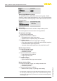


Table Of Contents
- 1 About this document
- 2 For your safety
- 3 Product description
- 4 Mounting
- 5 Connecting to power supply
- 5.1 Preparing the connection
- 5.2 Connecting
- 5.3 Wiring plan, single chamber housing
- 5.4 Wiring plan, double chamber housing
- 5.5 Double chamber housing Ex d
- 5.6 Wiring plan, double chamber housing Ex d ia
- 5.7 Double chamber housing with DISADAPT
- 5.8 Wiring plan - version IP 66/IP 68, 1 bar
- 5.9 Switch-on phase
- 6 Set up with the display and adjustment module
- 7 Setup with PACTware
- 8 Set up with other systems
- 9 Diagnosis, asset management and service
- 10 Dismount
- 11 Supplement

49
6 Set up with the display and adjustment module
VEGAPULS 69 • 4 … 20 mA/HART - two-wire
47247-EN-170315
4. For the full vessel, enter the distance value in m matching the
percentage value.
5. Save settings with [OK] and move with [ESC] and [->] to Min.
adjustment.
Proceed as follows:
1. Select with [->] the menu item "Min. adjustment"andconrmwith
[OK].
2. Edit the percentage value with [OK] and set the cursor to the
requested position with [->].
3. Set the requested percentage value with [+] and save with [OK].
The cursor jumps now to the distance value.
4. Enter the suitable distance value in m for the empty vessel (e.g.
distance from the sensor to the vessel bottom) corresponding to
the percentage value.
Todampprocess-dependentmeasuredvalueuctuations,setan
integration time of 0 … 999 s in this menu item.
The default setting is a damping of 0 s.
In the menu item "Currentoutputmode" you determine the output
characteristics and reaction of the current output in case of failure.
The default setting is output characteristics 4 … 20 mA, fault mode
< 3.6 mA.
Setup - Min. adjustment
Setup - Damping
Setup - Current output,
mode