
Instruction Manual


Quick Connect CCU Kit and WallVIEW Kit for the AW-HE120
© 2012 Vaddio - All Rights Reserved. Document Number 342-0498 Rev A Page 14 of 16
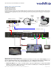
Appendix 1: Cable Pin-outs for the Quick-Connect CCU System
Quick-Connect CCU Pin-out Assignments:
Power Connector RJ-45
Pin Signal
1) Power +
2) Power -
3) Power +
4) Power -
5) Power +
6) Power -
7) Power +
8) Power -
RS-232 IN Connector RJ-45
Pin Signal - RS-232
1) Not Used
2) Not Used
3) Not Used
4) Not Used
5) Not Used
6) GND
7) RXD (from TXD)
8) TXD (to RXD)
RS-232 / G/L OUT Connector RJ-45
Pin Signal - RS-232
1) Not Used
2) Not Used
3) Not Used
4) G/L
5) G/L GND
6) GND
7) TXD (to RXD)
8) RXD (from TXD)
Video Connector RJ-45
Pin Signal
_______SD_______________HD______
1) CVBS + CVBS +
2) CVBS GND CVBS GND
3) Y+ Y+
4) C+ PB+
5) C GND PB GND
6) Y GND Y GND
7) Not Used PR+
8) Not Used PR-
12345678
12345678
12345678
12345678