
Quick-Connect Manual
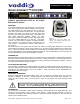


Quick-Connect CCU 300
Quick-Connect CCU 300 Installation and User Guide 341-741 Rev. B Page 9 of 12
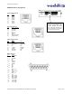
Appendix 1: Cable Pin-outs for the Quick-Connect CCU System
Quick-Connect CCU Pin-out Assignments:
Power Connector RJ-45
Pin
Signal
1) Power +
2) Power -
3) Power +
4) Power -
5) Power +
6) Power -
7) Power +
8) Power -
RS-232 IN Connector RJ-45
Pin
Signal - RS-232
1) Not Used
2) Not Used
3) Not Used
4) Not Used
5) Not Used
6) GND
7) RXD (from TXD)
8) TXD (to RXD)
RS-232 / G/L OUT Connector RJ-45
Pin
Signal - RS-232
1) Not Used
2) Not Used
3) Not Used
4) G/L
5) G/L GND
6) GND
7)
TXD (to RXD)
8)
RXD (from TXD)
Video Connector RJ-45
Pin
Signal
SD HD
1) CVBS + CVBS +
2) CVBS GND CVBS GND
3) Y+ Y+
4) C+ PB+
5) C GND PB GND
6) Y GND Y GND
7) Not Used PR+
8) Not Used PR-
12345678
12345678
12345678
12345678
300
200
POWER
36V
2.78A
>100
400+
Y-GAIN
CAM SELECT
Y
C
YPBPR
DISTANCE
CAMERA VIDEO ADJUST VIDEO OUTPUTS
VIDEO
COMP
CONTROL & EXT. SYNC
RS-232 IN RS-232 OUT
G/L OUT
G/L INPUTTALLY
+ G