
User's Manual


Digital UHF Driver/Transmitter Chapter 1, Introduction
LX Series, Rev. 1 1-1
Chapter 1:
Introduction
1.1: Manual Overview
This manual explains the installation,
setup, alignment, and maintenance
procedures for the LX Series modular
Digital UHF driver/transmitter. If your
transmitter contains external power
amplifier assemblies, then information
and drawings on the external amplifier
assemblies are contained in Volume 2.
This instruction manual is divided into
five chapters and supporting appendices.
Chapter 1: Introduction, contains
information on the assembly numbering
system used in the manual, safety,
maintenance, return procedures, and
warranties. Chapter 2: System
Description, maintenance and remote
control connections, describes the
transmitter and includes discussions on
system control and status indicators,
maintenance and remote control
connections. Chapter 3: Site
Considerations, installation and setup
procedures, explains how to unpack,
install, setup, and operate the
transmitter. Chapter 4: Circuit
Descriptions, contains circuit-level
descriptions for boards and board-level
components in the transmitter. Chapter
5: Detailed Alignment Procedures,
provides information on adjusting the
system assemblies for optimal operation.
Appendix A: contains drawings and
parts lists. Appendix B: contains a
transmitter log sheet
1.2: Assembly Designators
Axcera has assigned assembly numbers,
Ax designations such as A1, where
x=1,2,3…etc, to all assemblies, modules,
and boards in the system. These
designations are referenced in the text of
this manual and shown on the block
diagrams and interconnect drawings
provided in the appendices. The Block
Diagrams, Interconnects, Schematics,
Assembly Drawings and Parts Lists are
arranged in increasing numerical order in
the appendices. Section titles in the text
for assembly or module descriptions or
alignment procedures contain the
associated part number(s) and the
relevant appendix that contains the
drawings for that item.
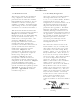
The cables that connect between the
boards within a tray or assembly and
that connect between the trays, racks
and cabinets are labeled using Brady
markers. Figure 1-1 is an example of a
Brady marked cable. There may be as
few as two or as many as four Markers
on any one cable. These Brady markers
are read starting furthest from the
connector. If there are four Brady
Markers, this marker is the transmitter
number such as transmitter 1 or
transmitter 2. The next or the furthest
Brady Marker is the rack or cabinet
number on an interconnect cable or the
board number within a tray. The next
number on an interconnect cable is the
Tray location or number. The Brady
marker closest to the connector is the
jack or connector number on an
interconnect cable or the jack or
connector number on the board within a
tray.
Figure 1-1: Brady Marker Identification
Drawing