
User's Manual


Innovator CU5-1800BTD/BRD ATSC Transmitter/ Initial On Site
Regenerative Translator Turn On Procedure
Instruction Manual, Rev. 0 23
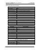
Signal Name
Pin
Designations
Signal Type Description
RMT
System Aural
Power Level
J12-10
Analog Output - 0 to 4.0 V- This is a
buffered loop through of the calibrated
“System Aural Power”. Indicates the
System Aural power. Scale factor is
100 % = 2.0V. (Not used in Digital)
Metering
RMT
System Reflected
Power Level
J12-11
Analog Output - 0 to 4.0 V- This is a
buffered loop through of the calibrated
“System Reflected Power”. Indicates
the System Reflected power.
Scale factor is 25 % = 2.0V.
Metering
RMT
Input Status
J12-12
Discrete Open Collector Output - A low
indicates that the Input to the System is
OK. Floating indicates an Input Fault.
Status
RMT
Fault Status
J12-13
Discrete Open Collector Output - A low
indicates that the System is OK.
Floating indicates a Fault has occurred.
Status
RMT
Operate Status
J12-14
Discrete Open Collector Output - A low
indicates that the System is in Standby.
Floating indicates the System is in
Operate.
Status
RMT Ground J12-15 Ground