
User's Manual


TOBY-R2 series - System Integration Manual
UBX-16010572 - R04 Design-in
Page 114 of 147
Examples of manufacturers offering compatible audio codec parts are the following:
Maxim Integrated (as the MAX9860, MAX9867, MAX9880A audio codecs)
Texas Instruments / National Semiconductor
Cirrus Logic / Wolfson Microelectronics
Nuvoton Technology
Asahi Kasei Microdevices
Realtek Semiconductor
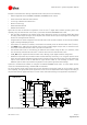
Figure 64 and Table 47 describe an application circuit for the I
2
S digital audio interface providing basic voice
capability using an external audio voice codec, in particular the Maxim MAX9860 audio codec.
DAC and ADC integrated in the external audio codec respectively converts an incoming digital data stream
to analog audio output through a mono amplifier and converts the microphone input signal to the digital bit
stream over the digital audio interface,
A digital side-tone mixer integrated in the external audio codec provides loopback of the microphones/ADC
signal to the DAC/headphone output.
The module’s I
2
S interface (I
2
S master) is connected to the related pins of the external audio codec (I
2
S slave).
The GPIO6 of the TOBY-R2 series module (that provides a suitable digital output clock) is connected to the
clock input of the external audio codec to provide clock reference.
The external audio codec is controlled by the TOBY-R2 series module using the DDC (I
2
C) interface, which
can concurrently communicate with other I
2
C devices and control an external audio codec.
The V_INT output supplies the external audio codec, defining proper digital interfaces voltage level.
Additional components are provided for EMC and ESD immunity conformity: a 10 nF bypass capacitor and a
series chip ferrite bead noise/EMI suppression filter provided on each microphone line input and speaker line
output of the external codec as described in Figure 64 and Table 47. The necessity of these or other
additional parts for EMC improvement may depend on the specific application board design.
Specific AT commands are available to configure the Maxim MAX9860 audio codec: for more details see the
u-blox AT Commands Manual [2], +UEXTDCONF AT command.
As various external audio codecs other than the one described in Figure 64 / Table 47 can be used to provide
voice capability, the appropriate specific application circuit has to be implemented and configured according to
the particular external digital audio device or audio codec used and according to the application requirements.
TOBY-R2 series
R2R1
BCLK
GND
U1
LRCLK
Audio
Codec
SDIN
SDOUT
SDA
SCL
MCLK
IRQn
R3
C3C2
C1
VDD
1V8
MICBIAS
C4
R4
C5
C6
MICLN
MICLP
D1
Microphone
Connector
MIC
C12 C11
J1
MICGND
R5
C8 C7
D2
SPK
Speaker
Connector
OUTP
OUTN
J2
C10 C9C14 C13
EMI3
EMI4
EMI1
EMI2
GPIO6
55
SDA
54
SCL
61
GND
5
V_INT
52
I2S_CLK
50
I2S_WA
51
I2S_TXD
53
I2S_RXD
Figure 64: I
2
S interface application circuit with an external audio codec to provide voice capability