
User Guide


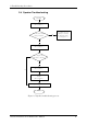


Table Of Contents
- Maintenance Manual - Streamline M (Intel)
- Chapter 1 - Hardware Overview
- Chapter 2 - Troubleshooting Procedures
- 2.1 Troubleshooting Introduction
- 2.2 Troubleshooting Flowchart
- 2.3 Power Supply Troubleshooting
- 2.4 Display Troubleshooting
- 2.5 Keyboard Troubleshooting
- 2.6 External USB Devices Troubleshooting
- 2.7 Touch pad Troubleshooting
- 2.8 Speaker Troubleshooting
- 2.9 Wireless LAN Troubleshooting
- 2.10 Camera Troubleshooting
- 2.11 Bluetooth Troubleshooting
- 2.12 4in1 card Troubleshooting
- 2.13 HDD Troubleshooting
- 2.14 CRT Troubleshooting
- 2.15 LAN Troubleshooting
- 2.16 MIC Troubleshooting
- 2.17 3D Sensor Troubleshooting
- 2.18 3G Troubleshooting
- 2.19 HDMI Troubleshooting
- 2.20 E-SATA Troubleshooting
- 2.21 Wimax Troubleshooting
- Chapter 3 - Tests and Diagnostic
- 3.1 The Diagnostic Test
- 3.2 Executing the Diagnostic Test
- 3.3 Display Configuration
- 3.4 Audio sound test
- 3.5 Fan ON/OFF Test
- 3.6 Main Battery Charge Test
- 3.7 FDD Test
- 3.8 Memory check
- 3.9 Keyboard Test
- 3.10 Mouse (Pad) Test
- 3.11 LCD Pixels Mode Test
- 3.12 Magnetic Switch Test
- 3.13 LAN Test
- 3.14 RTC Test
- 3.15 3D G-sensor test
- 3.16 HDD Test
- 3.17 Read DMI
- 3.18 Write DMI
- 3.19 Toshiba Logo set
- 3.20 Dynabook Logo set
- 3.21 TP TYPE R/W TEST
- 3.22 EE-PROM SETTING
- Chapter 4 - Replacement Procedures
- 4.1 General
- 4.2 Battery
- 4.3 HDD
- 4.4 Memory
- 4.5 Keyboard
- 4.6 Logic Upper Assembly
- 4.7 Touch Pad Bracket and TP Button Board
- 4.8 Power Board
- 4.9 RGB Board
- 4.10 WLAN Card
- 4.11 WWAN Card
- 4.12 Minicard Brackets
- 4.13 Display Assembly
- 4.14 USB & Audio Board
- 4.15 HDD Board
- 4.16 LED Board
- 4.17 Speakers
- 4.18 Bluetooth Combined With Cable Module
- 4.19 Thermal Fan
- 4.20 Motherboard
- 4.21 Thermal Module
- 4.22 LCD Bezel
- 4.23 LCD Module
- 4.24 Camera Module
- 4.25 Antennas for WLAN
- Appendix A - Handling the LCD Module
- Appendix B - Board Layout
- Appendix C - Pin Assignments
- Appendix D - Keyboard Scan/Character Codes
- Appendix E - Key Layout
- Appendix F - Series Screw Torque List
- Appendix G - Reliability

2 Troubleshooting Procedures
Satellite T230/T235 Series Maintenance Manual 22
To determine if the computer’s built-in TouchPad is functioning properly, perform the
following procedures. Figure 2-6 outlines the process. Start with Procedure 1 and continue as
instructed.
Procedure 1: Perform Touchpad test
Procedure 2: Touchpad connection check
Procedure 3: Touchpad replacement check
Procedure 1 Perform Touchpad test
Run the Diagnostic Program, which will automatically execute the Touchpad test. (Refer to
Chapter 3 system configuration check), Tests and Diagnostics for more information on the
program.
If an error is located, go to Procedure 2. If an error is not located, the Touchpad function is
functioning properly.
Procedure 2 Touchpad connection check
The Touchpad is connected via the Touchpad FPC to the system board. Make sure the
Touchpad FPC cable is firmly connected to the Touchpad and system board. Refer to Chapter
4, Replacement Procedures, for instructions on how to disassemble the computer and then
perform the following checks.
If any of the connections are loose, reconnect firmly. If any of the connections is damaged, or
there is still an error, go to Procedure 3.
Procedure 3 Touchpad replacement check
The Touchpad unit or FPC may be defective or damaged. Replace each with a new one
following the steps in Chapter 4. If the free-Dos test is still not functioning properly, replace
the system board with a new one following the steps in Chapter 4.