
User Guide
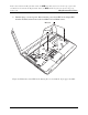


Table Of Contents
- Maintenance Manual - Streamline M (Intel)
- Chapter 1 - Hardware Overview
- Chapter 2 - Troubleshooting Procedures
- 2.1 Troubleshooting Introduction
- 2.2 Troubleshooting Flowchart
- 2.3 Power Supply Troubleshooting
- 2.4 Display Troubleshooting
- 2.5 Keyboard Troubleshooting
- 2.6 External USB Devices Troubleshooting
- 2.7 Touch pad Troubleshooting
- 2.8 Speaker Troubleshooting
- 2.9 Wireless LAN Troubleshooting
- 2.10 Camera Troubleshooting
- 2.11 Bluetooth Troubleshooting
- 2.12 4in1 card Troubleshooting
- 2.13 HDD Troubleshooting
- 2.14 CRT Troubleshooting
- 2.15 LAN Troubleshooting
- 2.16 MIC Troubleshooting
- 2.17 3D Sensor Troubleshooting
- 2.18 3G Troubleshooting
- 2.19 HDMI Troubleshooting
- 2.20 E-SATA Troubleshooting
- 2.21 Wimax Troubleshooting
- Chapter 3 - Tests and Diagnostic
- 3.1 The Diagnostic Test
- 3.2 Executing the Diagnostic Test
- 3.3 Display Configuration
- 3.4 Audio sound test
- 3.5 Fan ON/OFF Test
- 3.6 Main Battery Charge Test
- 3.7 FDD Test
- 3.8 Memory check
- 3.9 Keyboard Test
- 3.10 Mouse (Pad) Test
- 3.11 LCD Pixels Mode Test
- 3.12 Magnetic Switch Test
- 3.13 LAN Test
- 3.14 RTC Test
- 3.15 3D G-sensor test
- 3.16 HDD Test
- 3.17 Read DMI
- 3.18 Write DMI
- 3.19 Toshiba Logo set
- 3.20 Dynabook Logo set
- 3.21 TP TYPE R/W TEST
- 3.22 EE-PROM SETTING
- Chapter 4 - Replacement Procedures
- 4.1 General
- 4.2 Battery
- 4.3 HDD
- 4.4 Memory
- 4.5 Keyboard
- 4.6 Logic Upper Assembly
- 4.7 Touch Pad Bracket and TP Button Board
- 4.8 Power Board
- 4.9 RGB Board
- 4.10 WLAN Card
- 4.11 WWAN Card
- 4.12 Minicard Brackets
- 4.13 Display Assembly
- 4.14 USB & Audio Board
- 4.15 HDD Board
- 4.16 LED Board
- 4.17 Speakers
- 4.18 Bluetooth Combined With Cable Module
- 4.19 Thermal Fan
- 4.20 Motherboard
- 4.21 Thermal Module
- 4.22 LCD Bezel
- 4.23 LCD Module
- 4.24 Camera Module
- 4.25 Antennas for WLAN
- Appendix A - Handling the LCD Module
- Appendix B - Board Layout
- Appendix C - Pin Assignments
- Appendix D - Keyboard Scan/Character Codes
- Appendix E - Key Layout
- Appendix F - Series Screw Torque List
- Appendix G - Reliability

4 Replacement Procedures Fehler! Verwenden Sie die Registerkarte 'Start', um
標題
2 dem Text
zuzuweisen, der hier angezeigt werden soll. Fehler! Verwenden Sie die Registerkarte 'Start', um
標題
2 dem
Text zuzuweisen, der hier angezeigt werden soll.
2. Turn the logic upper assembly upside down. Remove one M2x4 screw and remove the
power board from the logic upper assembly.
M2×4*1
Figure 4.17 Removing the power board
Installing the Power Board
Install the Power Board according to the following procedures.
1. Seat the power board in the correct position on the logic upper assembly and secure it
with one M2x4 screw.
2. Insert the power board FFC into the slot on the logic upper assembly. Adhere the FFC to
the front of the logic upper assembly as shown in Figure 4.16.
Satellite/Satellite PRO T230 Maintenance Manual 4-30