
Air-Conditioner Service Manual


– 139 –
No.
W
Part name
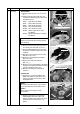
Drain pan
Procedure
1. Detachment
1) Perform works of items 1 of Q, 1 of R, 1
of
S and 1 of T.
2) Remove clamps of the lead wires con-
nected to the following connectors of the
control P.C. board.
CN34 : Float switch (3P: Red)
CN68 : Drain pump (3P: Blue)
CN101 : TC sensor (2P: Black)
CN102 : TCJ sensor (2P: Red)
CN333 : Power supply of fan motor
(5P: White)
CN334 : Position detection of fan motor
(5P: White)
NOTE :
Remove the connector by releasing locking
of the housing.
3) Remove screws fixing earth lead wire in
the electric parts box. (Ø4 x 6, 2 pcs.)
4) Remove indoor/outdoor inter-unit cable
and remote controller cable of the termi-
nal block.
5) Remove screws fixing the electric parts
box. (Ø4 x 10, 5 pcs.)
6) Remove screws fixing the bell mouth.
(Ø4 x 10, 6 pcs.)
7) Remove the drain cap, and drain water
accumulated in the drain pan.
NOTE 1 :
When removing the drain cap, be sure to
prepare a bucket to catch the drained water.
NOTE 2 :
Thermal insulator is adhered to the drain
cap. Be careful not to peel off the insulator.
If the insulator has been peeled, adhere it
with double-face tape, etc. as before.
8) Remove screws fixing the drain pan.
(Ø4 x 8, 4 pcs.)
2. Attachment
1) Fix the parts, drain cap, drain pan, bell
mouth, and electric parts box succes-
sively to their original positions.
2) Connect connectors, earth lead wire,
indoor/outdoor inter-unit cable, and
remote controller cable which have been
disconnected in the above item 1 as
before.
Remarks
Screws fixing earth lead wires
Drain cap
Screws fixing drain pan