
Operation Manual


– 27 –
<How to connect the connecting cable>
Wiring of the connecting cable can be carried out
without removing of the front panel.
(1) Remove the front panel.
Fully open the front panel. Disengage the
support arm located in the upper center while
pushing its handle leftwards, and then remove
the front panel toward you.
(2) Remove the terminal cover and cord clamp.
(3) Insert the connecting cable (according to local
codes) into pipe hole on the wall.
(4) Take out the connecting cable through the cable
slot on the rear panel so that it is exploded by
about 15 cm long in the front side.
(5) Insert the connecting cable fully into the terminal
block and secure it by screw tightly.
(6) Tightening torque:1,2 N•m (0,12 kgf•m)
(7) Secure the connecting cable with the cord clamp.
(8) Fix the terminal cover and front panel on the
indoor unit.
CAUTION
• Be sure to refer the wiring system diagram
labeled inside the front panel.
• Check local electrical codes and also any
specific wiring instructions or limitation.
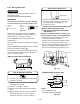
For a three conductor cable
NOTE :
• Use stranded wire only.
• Wire type:More than H05 RN-F
Fig. 8-4-10
10mm
40mm
50mm
10mm
Earth line
1
2
Fig. 8-4-9
<Stripping length of connecting cable>
<How to install the front cabinet on the
indoor unit>
Install the front cabinet through the opposite order of
“How to remove the front cabinet”.
When the panel is removed and mounted again, take
the following actions:
After fastening the two screws, one each at the left
and right of the air outlet, be sure to push the upper
center
Q
right end
R
, left end
S
and the lower
center
T
of the air outlet, and confirm that no gap is
left between the front cabinet and the rear plate.
• If cooling (dry) operation is made without
pushing the air outlet, dew can be deposited on
the front cabinet surface. In addition a gap
between the front cabinet and the rear plate will
become wider, spoiling the appearance.
3
1
2
4
Push Push
Push
Push
Fig. 8-4-11
8-4-4. Piping and Drain Hose Installation
<In case of rightward piping>
• After scribing slits of the front panel and the rear
panel by a knife or a marking-off pin, cut them by a
pair of nippers or the like.
Fig. 8-4-13
Slit
(rear panel)
Slit
(front panel)
Slit (rear panel)
Slit (front panel)
Fig. 8-4-12
<In case of downward piping>
• After scribing the slit of the front panel and slit in
the lower part of the rear panel by a knife or a
marking-off pin, cut them by a pair of nippers or the
like.
Terminal block
Cord
clamp
Screw
Screw
Connecting cable
Earth
line
Terminal
cover
Screw
2
1
Connecting
cable
about 15cm