
LCD Color TV Owner's Manual


26
Connecting your TV
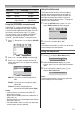
Side connections
You can connect a wide variety of auxiliary
equipment via the terminals located on the right
side of the panel o (2).
Please always refer to the owner’s manual of the
equipment to be connected for full details.
Connection example
TV right side view
Video Games
Camcorder Camcorder with
S-Video
• To select the side inputs, press o until the
video input mode list appears on the screen,
then press u or U to select o2 (- page 23),
then press Q.
• Before connecting any external equipment, turn
off all main power switches.
• Connect either the S-VIDEO or VIDEO input
terminal, whichever terminal is used. Never
connect both terminals at a time.
• If you connect mono sound equipment to
o (2), connect the audio output of the
equipment to the L/MONO jack on the TV.
• You can enjoy Video Games with this TV.
However shooting games, where the player
shoots at a target on the TV screen with a light
gun, may not work because of the LCD Color
TV properties.
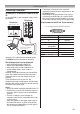
Back connections
Connection example
COMPONENT
VIDEO INPUT
COMPONENT
VIDEO INPUT
PC/HDMI1
(AUDIO)
MONITOR
P
B
/C
B
P
B
/C
B
P
R
/C
R
P
R
/C
R
Y
Y
R
R
R
R
L
VIDEO
VIDEO
L/MONOL/MONO
L
/MONO
AUDIOAUDIO
AUDIO
(3) (1)
TV back view
DVD video player
(with component
video outputs)
Set Top Box
VCR
(Recording)
DVI device
HDMI device
TV back view
• Before connecting any external equipment, turn
off all main power switches.
• The unauthorized recording of television
programs, DVDs, video tapes and other
materials may infringe upon the provisions of
copyright law.
• If you connect both of the COMPONENT
VIDEO INPUT terminal and VIDEO input
terminal o (1), the COMPONENT VIDEO
signal will appear on the screen (display
changes to o 1C).
• The COMPONENT VIDEO INPUT consists of
three component video signals (Y, P
B/CB, PR/
C
R) and provides the best picture performance.
These terminals can only be used with the
component video compatible equipment e.g.
DVD video player, etc.
• Additional equipment and cables shown are not
supplied with this TV.