
Service Manual


Hold pintle assembly in position against cover and
remove motor rotor assembly.
IMPORTANT:
Each ball must
be
replaced in same bore
from which
it
was removed. Use egg carton for ball
Inspect rotor assembly. Remove piston balls from
rotor, one at a time, working clockwise from letter
stamped in face of rotor and place in egg carton.
inspect ball pistons. They must be smooth and free
from any marks.
Inspect rotor bores, bushing and pintle for damage
or excessive clearance. Ball piston to rotor bore clear-
ance
is
select
fit
to
.0002-.0006".
When damage
is
found, replace complete rotor assembly.
If
damage
is
not found, reinstall balls in their removed bores and
retain with rubber band.
storage and identification.
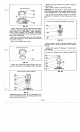
PINTLE REMOVAL
FIG.
46
IMPORTANT:
Pump rotor piston balls must remain in
pump rotor, a repeat of previous Motor rotor assembly.
Use second rubber band to retain piston balls.
Make sure pump rotor remains in cover and tap on
cover with plastic hammer to remove pintle assembly.
Place rubber band on motor rotor assembly.
RELIEF VALVE REMOVAL/INSPECTION
Relief Valve
Plug
DO
NOT
REMOVE
Plugs
(2)
Ball
Pintle
FIG.
47
WE DO NOT RECOMMEND COMPLETE DISASSEMBLY
OF
PINTLE
ASSEMBLY FOR CLEANING, FLUSHING
QUIRED, USE FOLLOWING
PINTLE
DISASSEMBLY AND
Do
not remove two large plugs located on pintle
journal.
Use a
1/4”
Allen wrench to remove relief valve plug.
Remove spring and ball. Inspect ball seat and all parts
for damage. Replace any damaged parts.
SHOULD BE ALL THAT
IS
NEEDED. IF REPAIR
IS
RE-
INSTALLATION PROCEDURES.
Install ball, spring and plug into pintle. SCREW
PLUG
END
IN
JUST BELOW SURFACE
OF
PINTLE,
DO
NOT TIGHTEN COMPLETELY.
DAMPENING PISTONS REMOVAL/INSTALLATION
FIG.
48
IMPORTANT:
When removing dampening piston,
do
not hit pintle journals or damage to pintle
will
occur.
To remove dampening pistons, use adhesive to ce-
ment a bolt or similar object to pistons and pull them
from pintle bores. Remove back-up rings and O-rings
from pistons. Replace pistons
if
damaged.
Install new back-up rings nearest to smooth piston
face and O-rings in groove on pistons.
Lubricate outer surface of pistons and press pistons
into pintle bores with smooth face up. Piston smooth
face should
be
flush with pintle surface.
CHECK
a
ACCELERATION
VALVES
FIG.
49
Press coil pin and solid pin from pintle housing.
CHECK VALVE BALLS REMOVAL
Rod
3/16”Dia. Check Valve Body
Check Valve
Ball
FIG.
50
-22