
Installation Instructions


5
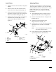
5. Position the chute bumper against the left inside
of the cover, with the end formed outward as
shown (Fig. 6 and 7).
6. Secure the chute bumper to the cover with (2)
1/4-20 x 3/4” bolts and (2) 1/4-20 flange
locknuts (Fig. 6 and 7).
1
m-3964
4
3
2
Figure 7
1. PTO
cover
2.
Chute bumper
3.
Bolt1/4-20 x 3/4” (19 mm)
4.
Flange locknut 1/4-20
7. Install the PTO cover onto the cover support
with (2) 5/16–18 x 27/64” (11 mm) shoulder
bolts and (2) 5/16–18 flange locknuts (Fig. 6).
Modify Chute
1. Remove the narrow latch from the chute and
discard.
2. Measure for hole location as shown (Fig. 8).
3. Mark and drill a 9/32” (7.5 mm) hole in the
chute, as shown, for the short spring bracket
(Fig. 8).
4. Place the 1/4” (6 mm) washer and 1/4-20 x 3/4”
(19 mm) bolt through the hole from the inside of
the chute and secure the short spring bracket to
the bolt with a 1/4-20 locknut (Fig. 8).
m–4000
5
2
1
3
4
6
7
Figure 8
1. 2-5/8”
(57 mm)
2.
5-7/8” (149 mm)
3.
Mark and drill 9/32” (7.5
mm) hole in chute
4.
Bolt 1/4-20 x 3/4” (19 mm)
5. W
asher 1/4” (6 mm)
6.
Spring bracket–short
7.
Locknut 1/4-20