
Operator's Manual


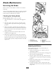

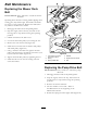

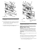


Figure68
1.Switchscrews
3.Nutandbolt
2.Cam
9.Afterthecamisadjusted,theleverswitchneedsto
bechecked.
10.Checkthegapbetweenthecontrolleverandswitch
asshowninFigure69.Thegapneedstobean1/8
inch(3mm)withtherightmotioncontrolleverin
theneutral,unlockedposition.
11.Ifneeded,loosenthescrewsholdingtheswitchand
adjusttheswitch(
Figure68andFigure69).
Figure69
1.Switch
3.Rightmotioncontrollever
intheneutralunlocked
position
2.1/8inch(3mm)
12.Tightentheswitchscrews.
AdjustingtheNeutralPostionforthe
MotionControlLevers
Important:Ensurethetrackingofthemoweris
correctafteradjustingthemotioncontrollevers.
Adjustingthetrackingandaligningthemotion
controlleversfronttobackisthesameprocedure
(Figure70).
Note:Adjustthehorizontalalignmentbeforethefront
tobackalignment.
Ifthemotioncontrolleversdonotalignfronttoback,
ortherightsidecontrolleverdoesnotmoveeasilyinto
theneutrallockposition,adjustmentisrequired.
1.Afterthehorizontalalignmentisnished,checkthe
fronttobackalignment(Figure70).
49