
Operator's Manual


1
2
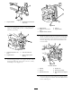
G010578
Figure11
1.Supportbracket2.Selftappingscrews(5/16
x3/4inch)
3.Installtheangledbaggerbrackettotheengineguard
usingtwocarriagebolts(5/16x3/4inch)andtwo
locknuts(5/16inch).
G014882
1
2
3
4
Figure12
1.Carriagebolt(5/16x3/4
inch)
3.Locknut(5/16inch)
2.Angledbracket4.Holeinengineguard,
existing
4.Installthebaggerframetothesupportbracket.Secure
thebaggerframewithaclevispin(1/2x2-1/4inch)
andhairpincotter(Figure13).
G014884
1
2
3
4
5
Figure13
1.Baggerframe
4.Hairpin
2.Clevispin(1/2x2-1/4
inch)
5.Anglebracket
3.Supportbracket,receiver
5.Installtwosupportrods,onetoeachsideofthebagger
frame.Locatetheexistingkeyedslotinthemachine
frameandinstallthebent,aredendoftherodinto
thatslot(Figure14).Movetherodrearwardtoseat
itintheframe.
G014885
1
2
3
4
5
6
Figure14
Leftsideshown
1.Washer
4.Supportrod
2.Hairpin5.Keyedslot,existing
3.Bracketframehole6.Bent,aredendofsupport
rod
6.Insertthebentendsoftherodintothebaggerframe
asshowninFigure14.Securetheendoftherodwitha
washerandhairpin.
9