
Operator's Manual


G020767
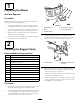
Figure6
1.Baggerframe5.Clevispin(1/2x2-1/4
inch)
2.Removetheexisting
rectangularspacerplate
(ifsoequipped)
6.Newspacerplate
3.Hairpin
7.Existingfasteners
4.Supportbracket
7.Installtwosupportrods,onetoeachsideofthebagger
frame.Locatetheexistingbracketbetweentherear
drivewheelandframe(Figure7).
G020997
5
6
4
1 2 3
1
Figure7
Leftsideshown
1.Baggerframe
4.Hairpin
2.Clevisend5.Bracketonframe
3.Clevispin(1/2x1-1/2
inch)
6.Washer
8.Insertthebentendsoftherodintothebaggerframe
asshowninFigure7.Securetheendoftherodwitha
washerandhairpincotterpin.
9.Adjustthesupportrodssothatbaggerframeisheld
securetothemachineframeandsitsinthenotchof
theanglespacerplateinstalledpreviously.Repeatthese
stepsforeachsupportrod:
A.Loosenthejamnutatthebaseoftheclevisend
oftherod.
B.Rotatetheclevisendoftherodtoadjusttherod
tothedesiredlength.
C.Aligntheholesintheclevisendwiththeholein
thebaggerframeattheattachmentpoint.
D.Securetheclevisendoftherodstothebagger
frameusingaclevispinandhairpincotter
pin(
Figure7).
E.Tightenthejamnut.
10.Withbothrodsinstalledandattached,checkthebagger
frameforplay.Thebaggerframeshouldbeheldtight
tothemachineframe.Ifnecessary,repeattheprevious
steptosecurethebaggerframe.
8