
Operator's Manual


7
m–6619
1
2
3
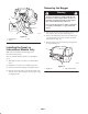
Figure 9
1. Grass deflector
2. Pivot rod
3. Nut
4. Insert the new pivot rod into the short stand-off on the
deck. Secure the rear end of rod into the mower with a
nut (3/8 inch) (Fig. 10).
m–6618
2
3
1
4
5
Figure 10
1. Mower
2. Pivot rod
3. Nut
4. Stand off
5. Right side blade
Installing the Blades for Model
79214 Only (42 inch Mower)
1. Hold the blade using a rag or thickly-padded glove
(Figures 10 and 11).
2. Remove the blade bolt, curved washer, blade stiffener,
and blade from the spindle shaft (Fig. 11).
3. Install the blade onto the spindle shaft (Fig. 11).
Important The curved part of the blade must be
pointing upward toward the inside of the mower to ensure
proper cutting.
4. Install the blade stiffener, the curved washer (cupped
side toward the blade) and the blade bolt (Fig. 11).
Torque the blade bolt to 35–65 ft-lb (47–88 N⋅m).
5. Repeat steps 1 through 4 for the opposite blade.
m–6430
1
2
5
3
4
Figure 11
1. Sail area of blade
2. Blade
3. Curved washer
4. Blade bolt
5. Blade stiffener
Installing the Chute and
Discharge Tube
1. Slide the chute into position with the rear hook around
the deflector rod and the front latch aligned. Insert the
locking pin (Fig. 12).
2. Hook the flexible latch on the chute into the notched
bracket on the back of the mower (Fig. 12)
m–3406 1
2
5
6
3
4
Figure 12
1. Chute
2. Locking pin
3. Rear hook
4. Deflector rod
5. Flexible latch
6. Notched bracket
3. Slide the discharge tube into the opening in the grass
catcher (Fig. 13).
4. Slide the discharge tube over the end of the chute,
ensuring that the tab on the chute snaps into the square
hole in the discharge tube (Fig. 13).