
Operator's Manual


Note:Formostconditions,adjusttheback
bladetip4mm(1/4inch)higherthanthefront.
15.Torquethe2boltsto37to45N∙m(27to33ft-lb).
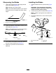
16.Onbothsidesofthedeck,measurefromthe
levelsurfacetothebacktipoftheblade(position
B)asshowninFigure85.
Note:Themeasurementshouldread8.3cm
(3-1/4inches)
17.Fine-tunethescrewadjusterbyturningittoget
8.3mm(3-1/4inches)height(Figure86).
Note:T oincreasetheheight,turnthe
adjustmentnutclockwise;todecreasethe
height,turnitcounterclockwise.
18.Measureuntilall4sidesarethecorrectheight.
19.Tightenallthenutsonthedeck-lift-arm
assemblies.
20.Lowerthedischargechute.
ServicingtheCutting
Blades
Toensureasuperiorqualityofcut,keeptheblades
sharp.Forconvenientsharpeningandreplacement,
keepextrabladesonhand.
WARNING
Awornordamagedbladecanbreak,anda
pieceofthebladecouldbethrownatyou
orbystanders,resultinginseriouspersonal
injuryordeath.
•Inspectthebladesperiodicallyforwearor
damage.
•Replaceawornordamagedblade.
BeforeInspectingorServicingthe
Blades
1.Parkthemachineonalevelsurface,Disengage
theblade-controlswitch(PTO),andsetthe
parkingbrake.
2.Turntheignitionkeytooff.Removethekey,and
disconnectthesparkplugwiresfromthespark
plugs.
InspectingtheBlades
ServiceInterval:Beforeeachuseordaily
1.Inspectthecuttingedges(Figure89).
2.Iftheedgesarenotsharporhavenicks,remove
andsharpentheblade;refertoRemovingthe
Blades(page67)andSharpeningtheBlades
(page68).
3.Inspecttheblades,especiallyinthecurvedarea.
4.Ifyounoticeanycracks,wear,oraslotforming
inthisarea,immediatelyinstallanewblade
(Figure89).
g006530
Figure89
1.Cuttingedge3.Wear/slotforming
2.Curvedarea4.Crack
66