
Operator's Manual


ControlsSystem
Maintenance
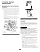
AdjustingtheControlHandle
Position
Thereare2heightpositionsforthecontrollevers:highand
low .Removetheboltstoadjusttheheightfortheoperator.
1.DisengagethePTO,movethemotioncontrolleversto
theneutrallockedposition,andsettheparkingbrake.
2.Stoptheengine,removethekey,andwaitforallmoving
partstostopbeforeleavingtheoperatingposition.
3.Loosentheboltsandangenutsinstalledinthelevers
(Figure84).
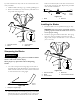
4.Alignthefront-to-rearpositionoftheleversby
bringingtheleverstogethertotheneutralpositionand
slidingthemuntiltheyarealigned;thentightenthe
bolts(Figure85).
Figure84
1.Bolt
3.Controllever
2.Handle4.Nut
Figure85
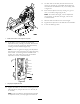
AdjustingtheMotionControl
Linkage
Locatedoneithersideofthefueltank,belowtheseatare
thepumpcontrollinkages.Rotatingthepumplinkagewitha
1/2inchwrenchallowsnetuningadjustmentssothatthe
machinedoesnotmoveinneutral.Anyadjustmentsshould
bemadeforneutralpositioningonly.
WARNING
Theenginemustberunningandthedrivewheels
mustbeturningsothatthemotioncontrol
adjustmentcanbeperformed.Contactwithmoving
partsorhotsurfacesmaycausepersonalinjury.
Keepngers,hands,andclothingclearofrotating
componentsandhotsurfaces.
1.Priortostartingtheengine,pushthedeckliftpedal,
removetheheight-of-cutpin,andlowerthedeckto
theground.
2.Raisetherearofthemachineupandsupportitwith
jackstands(orequivalentsupport)justhighenoughto
allowthedrivewheelstoturnfreely.
3.Removetheelectricalconnectionfromtheseatsafety
switch,locatedunderthebottomcushionoftheseat.
Note:Theswitchisapartoftheseatassembly.
4.Temporarilyinstallajumperwireacrosstheterminals
intheconnectorofthemainwiringharness.
5.Starttheengine.
Note:Thebrakemustbeengaged,andthe
motioncontrolleversout,tostarttheengine.The
operatordoesnothavetobeintheseatbecauseof
52