
Operator's Manual


Assembly
7
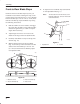
10. Remove hairpin cotters from trunnion and
bottom of yoke (Fig. 7).
11. Unlatch and remove locking clevis pin that
secures yoke assembly to clutch shaft. Pivot
yoke out and forward to remove from clutch
shaft and engagement plate (Fig. 7).
12. Place belt in inside pulley groove (Fig. 7).
13. Assemble yoke and engagement plate and attach
locking clevis pin, trunnion and hairpin cotters
to secure (Fig. 7).
m–3443
1
2
3
4
1
7
6
5
Figure 7
1. Hairpin cotter
2. Trunnion
3. Engagement plate
4. Locking clevis pin
5. Yoke
6. Clutch shaft
7. Inside groove
14. Place pulley assembly into front hitch and lock
by moving latch rearward (Fig. 8).
2
1
m–2810
3
Figure 8
1. Pulley assembly
2. Front hitch
3. Latch
15. Route belt around V and flat pulleys and loop
over center mower spindle, top pulley.(Fig. 9).
16. Check that spacer is on shaft and install belt
cover with rod in hole. Secure with locknut
(Fig. 9).
17. Turn knob counterclockwise to tighten belt
(Fig. 9). Tighten until there is 1” (26 mm) belt
movement between engine clutch and idler
pulley when slight pressure is applied to the belt.
2
1
m-2823
3
7
4
5
6
Figure 9
1. V pulley
2. Flat pulley
3. Upper mower pulley
4. Spacer
5. Belt cover
6. Locknut
7. Knob
18. Install belt cover (Fig. 6).